Milling cutter type cable stripper

A stripper and milling cutter technology, which is applied in the directions of circuit/collector parts, cable installation, cable installation device, etc. Simple, low physical exertion for workers

Active Publication Date: 2016-06-08
国网山东省电力公司聊城供电公司
View PDF8 Cites 8 Cited by
  • Summary
  • Abstract
  • Description
  • Claims
  • Application Information

AI Technical Summary

Problems solved by technology

Now there are special tools for fixing the tool to a specific bracket on the market, but its actual use effect is not good, and the disadvantages are as follows
[0003] 1. The wires currently used are generally cross-linked polyethylene cables or polyethylene insulated wires. The hardness of the material is very large

Method used


Image

  • Milling cutter type cable stripper
  • Milling cutter type cable stripper
  • Milling cutter type cable stripper

Examples


Example Embodiment

[0027] The present invention will be further described below in conjunction with the drawings and embodiments.

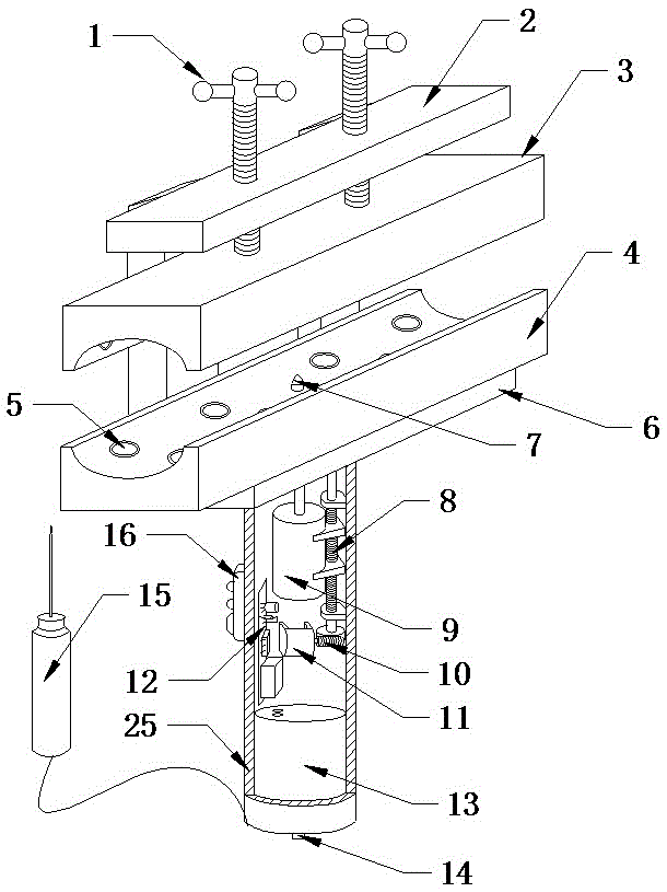
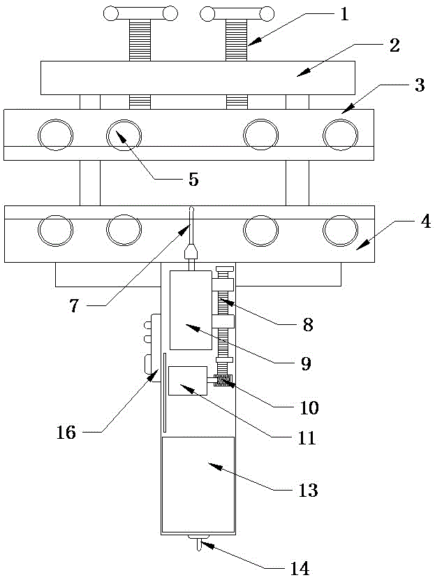
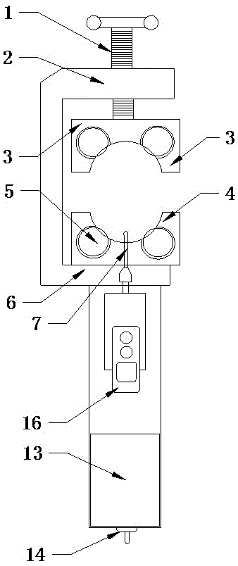
[0028] Such as Figure 1-Figure 3 As shown, the milling cutter type cable stripper of this embodiment is composed of six parts: a cable holding device, a milling cutter 7 and a milling cutter motor 9, a milling cutter stroke control device, a control circuit, a power battery 13 and a housing 25 .

[0029] This embodiment specifically includes a compression bolt 1, an upper fixing frame 2, an upper compression plate 3, a lower compression plate 4, a spherical bull's eye bearing 5, a lower fixing frame 6, a milling cutter 7, a milling cutter motor guide 8, and a milling cutter Motor 9, turbo reducer 10, rail motor 11, control circuit board 12, power battery 13, main power switch 14, auxiliary electrode pin 15, function switch 16, milling cutter motor switch 17, rail switch 18, central logic control circuit 19. Milling cutter motor control circuit 20, guide rail motor sto...


PUM


Abstract

The invention discloses a milling cutter type cable stripper. The milling cutter type cable stripper comprises a cable clamping device, a milling cutter (7) and a milling cutter motor (9), wherein the cable clamping device comprises hold-down bolts (1), an upper fixing rack (2), an upper hold-down plate (3), a lower hold-down plate (4) and a lower fixing rack (6); the upper fixing rack (2) and the lower fixing rack (6) are fixedly connected, the lower hold-down plate (4) is fixed on the lower fixing rack (6), the upper hold-down plate (3) is fixed on the upper fixing rack (2) through the hold-down bolts (1), the upper hold-down plate (3) and the lower hold-down plate (4) are arranged correspondingly, the milling cutter (7) is driven by the milling cutter motor (9), and a cutting head of the milling cutter (7) penetrates through the lower fixing rack (6) and the lower hold-down plate (4). The milling cutter type cable stripper is simple and reliable to operate, labor-saving and effort-saving, hardly damages a cable conductor, controls the milling stripping thickness automatically, hardly damages a wire, and does not have a hand injury risk due to the fact that the milling cutter is arranged in the hold-down plate.

Description

technical field [0001] The invention relates to an electric construction tool. Background technique [0002] In the construction of cables and insulated wires, such as the connection between wires, the connection between wires and equipment, etc., it is necessary to remove the wire insulation layer. Traditional construction methods are generally done manually using electrician tools. There are special tools for fixing the cutting tool to a specific bracket on the market now, but its actual use effect is not good, and the disadvantages are as follows. [0003] 1. The conductors currently used are generally cross-linked polyethylene cables or polyethylene insulated conductors. The material is very hard, and it is very difficult to strip it with a knife, and the efficacy is low. [0004] 2. The special tools are also hand tools, and the construction is time-consuming and laborious. [0005] 3. The thickness is not easy to control, and the conductor is often damaged. [0006...

Claims


Application Information

Patent Timeline
IPC IPC(8): H02G1/12H01R43/28
CPCH01R43/28H02G1/1268
Inventor 迟卫庆刘国平白玉庆唐晓张茂元庞金虎张海涛
Owner 国网山东省电力公司聊城供电公司
Why Eureka
Try Eureka