WLAN (Wireless Local Area Network) transmission system and signal transmission method for WLAN system

A transmission system and signal receiving technology, which is applied in the transmission system, wireless communication, power management, etc., can solve problems such as incorrect antenna installation or shaking during travel, and the effective sending and receiving distance of WLAN cannot reach 190m, so as to reduce the impact and reduce the Circuit, the effect of increasing the use time

Active Publication Date: 2016-06-08
SHENZHEN SIECOM COMM TECH DEV CO LTD
View PDF4 Cites 19 Cited by
  • Summary
  • Abstract
  • Description
  • Claims
  • Application Information

AI Technical Summary

Problems solved by technology

[0013] However, in the actual application environment, due to the attenuation caused by uncertain factors such as trees and buildings, absorption attenuation of building materials, energy absorption attenuation of water bodies, improper installation of antennas or shaking during travel, etc. For stable data transmission and control, the fading reserve M will be far greater than 0dbm, so the actual effective sending and receiving distance of WLAN cannot reach 190m

Method used


Image

  • WLAN (Wireless Local Area Network) transmission system and signal transmission method for WLAN system
  • WLAN (Wireless Local Area Network) transmission system and signal transmission method for WLAN system
  • WLAN (Wireless Local Area Network) transmission system and signal transmission method for WLAN system

Examples


Embodiment 1

[0051] Please refer to Figure 2 to Figure 4 , Embodiment 1 of the present invention is:

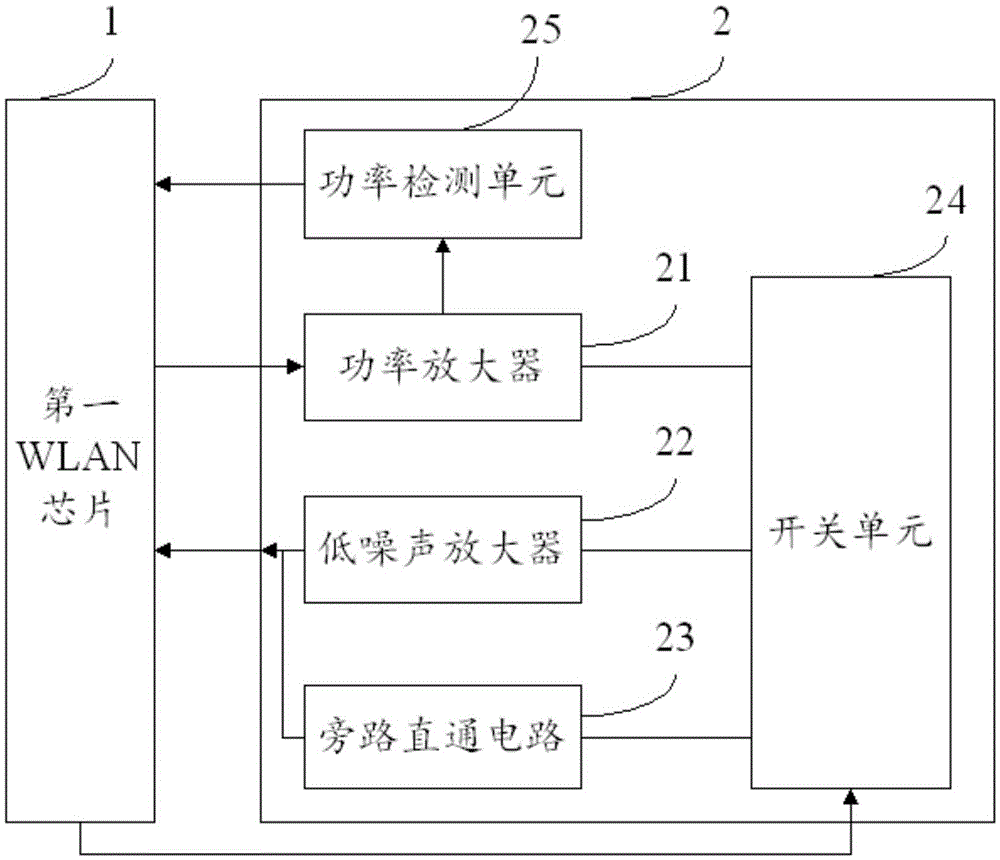
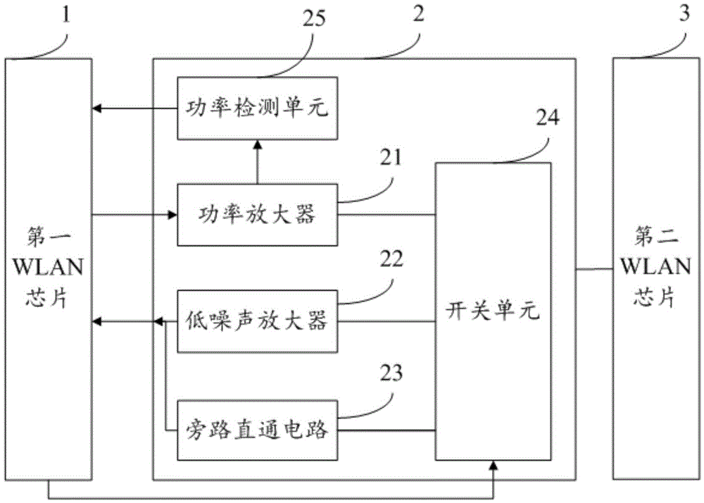
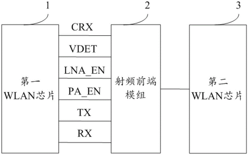
[0052] A WLAN transmission system, comprising: a radio frequency front-end module 2, a first WLAN chip 1 and a second WLAN chip 3; the radio frequency front-end module 2 comprises: a power amplifier 21, a low noise amplifier 22, a bypass direct circuit 23. A switch unit 24 and a power detection unit 25, the switch unit 24 is a three-choice one-on switch, which can respectively turn on the paths of the power amplifier 21, the low-noise amplifier 22 and the bypass direct circuit 23, The input end of the power amplifier 21 is connected with the transmitting end TX of the first WLAN chip 1, and the output end is connected with the receiving end RX of the second WLAN chip 3; the output end of the low noise amplifier 22 is connected with the first WLAN chip 1 The receiving end RX of the first WLAN chip 1 is connected, and the input end is connected to the transmitting end TX of the second WLA...

Embodiment 2

[0056] A signal transmission method of a WLAN system, the WLAN system includes a radio frequency front-end module 2, a first WLAN chip 1 and a second WLAN chip 3, the radio frequency front-end module 2 includes a power amplifier 21, a low noise amplifier 22 , a bypass direct circuit 23 and a switch unit 24; including:

[0057] When the first WLAN chip 1 transmits a signal, the low noise amplifier 22 is turned off, and the first WLAN chip 1 judges whether the signal-to-noise ratio of the received signal of the second WLAN chip 3 is greater than the first target signal-to-noise ratio, and if so, the power amplifier 21 reduces The power of the small transmitted signal; if not, the power amplifier 21 increases the power of the transmitted signal;

[0058] When the first WLAN chip 1 receives a signal, judge whether to turn on the low noise amplifier 22 according to the received signal strength indication;

[0059] If the strength of the received signal is less than the decision le...


PUM


Abstract

The invention discloses a WLAN (Wireless Local Area Network) transmission system, which is characterized by comprising a radio frequency front end module and a first WLAN chip, wherein the radio frequency front end module comprises a power amplifier, a low noise amplifier, a bypass through circuit and a switch unit, wherein the switch unit is respectively connected to the power amplifier, the low noise amplifier and the bypass through circuit, and an input end of the power amplifier is connected to a transmitting end of the first WLAN chip; an output end of the low-noise amplifier is connected to a receiving end of the first WLAN chip; one end of the bypass through circuit is connected to the receiving end of the first WLAN chip; and the switch unit is connected to a control end of the first WLAN chip. The invention also relates to a signal transmission method for a WLAN system, the power of a transmitting signal and the power of a receiving signal can be adjusted to realize the communication requirements for increasing a communication distance and guaranteeing the communication quality.

Description

technical field [0001] The present invention relates to the technical field of wireless communication, in particular to a WLAN transmission system and a signal transmission method of the WLAN system. Background technique [0002] In the current UAV application, data transmission and control commands are transmitted through WLAN. Most of the WLANIC internal integrated power amplifiers (PA) on the market currently have very limited transmission power, so they can only be transmitted within a very short distance. . At present, if the WLAN chip solution on the market is used on a drone, the transmission distance will be too short to realize long-distance data transmission and control. In order to increase the transmission distance, a repeater is added between the drone and the controller to increase the transmission distance, which will increase the cost. At the same time, the position of the repeater must be constantly changed according to the position of the drone, causing ma...

Claims


Application Information

Patent Timeline
Patent Type & Authority Applications(China)
IPC IPC(8): H04W52/24H04B1/40H04W84/12
CPCH04B1/40H04W52/245H04W84/12
Inventor 郑大英马喜奎邓维维刘浩方萃松李磊
Owner SHENZHEN SIECOM COMM TECH DEV CO LTD
Why Eureka
Try Eureka