
An optomagnetic double resonance device

A dual-resonance, optical-magnetic technology, applied in the directions of magnetic resonance measurement, magnetic variable adjustment, and magnetic variable measurement, can solve the problems of unstable beam frequency, lower signal-to-noise ratio, and inaccurate information, so as to improve sensitivity and Measurement accuracy and the effect of improving the signal-to-noise ratio

Active Publication Date: 2015-01-14
PEKING UNIV
View PDF0 Cites 14 Cited by
  • Summary
  • Abstract
  • Description
  • Claims
  • Application Information

AI Technical Summary

Problems solved by technology

[0005] Defects of traditional opto-magnetic dual resonance devices: the light beam generated by the light source module has a certain intensity noise, and the frequency of the light beam is also unstable, which is easily disturbed by the outside world, which will directly affect the stability of the detection signal and increase the noise in the signal. Secondly, in the atomic system module, since the working state of the atomic gas chamber inside the module will change with time, the light intensity after passing through the atomic gas chamber will also change to a certain extent, which will also introduce Additional noise, so for the traditional optomagnetic double resonance device, the above defects will greatly reduce the signal-to-noise ratio of the signal detected by the device, which directly leads to the inaccuracy of the extracted information. In some occasions that require very high detection sensitivity, The traditional optomagnetic double resonance device is no longer applicable

Method used


Image

  • An optomagnetic double resonance device
  • An optomagnetic double resonance device

Examples


Embodiment Construction

[0017] The present invention will be described in further detail below in conjunction with the accompanying drawings. It is necessary to point out that the following specific embodiments are only used to further illustrate the present invention, and cannot be interpreted as limiting the protection scope of the present invention. Those of ordinary skill in the art can Some non-essential improvements and adjustments are made to the present invention according to the above-mentioned content of the invention.

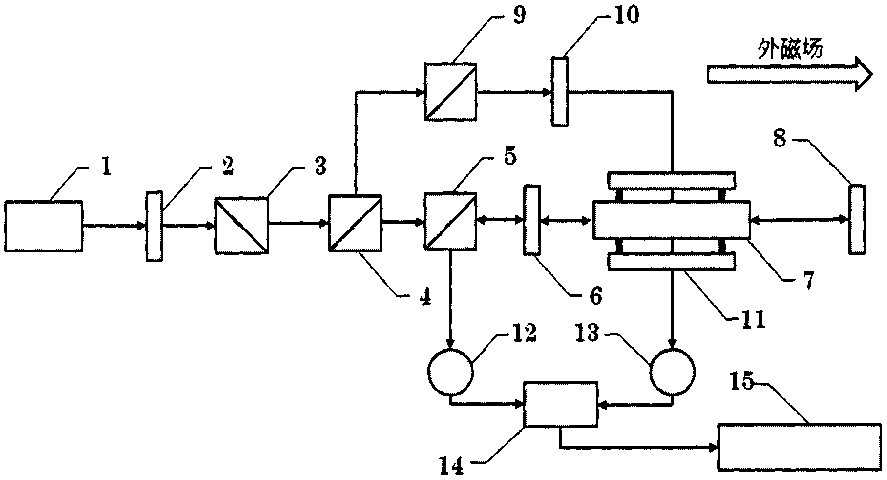
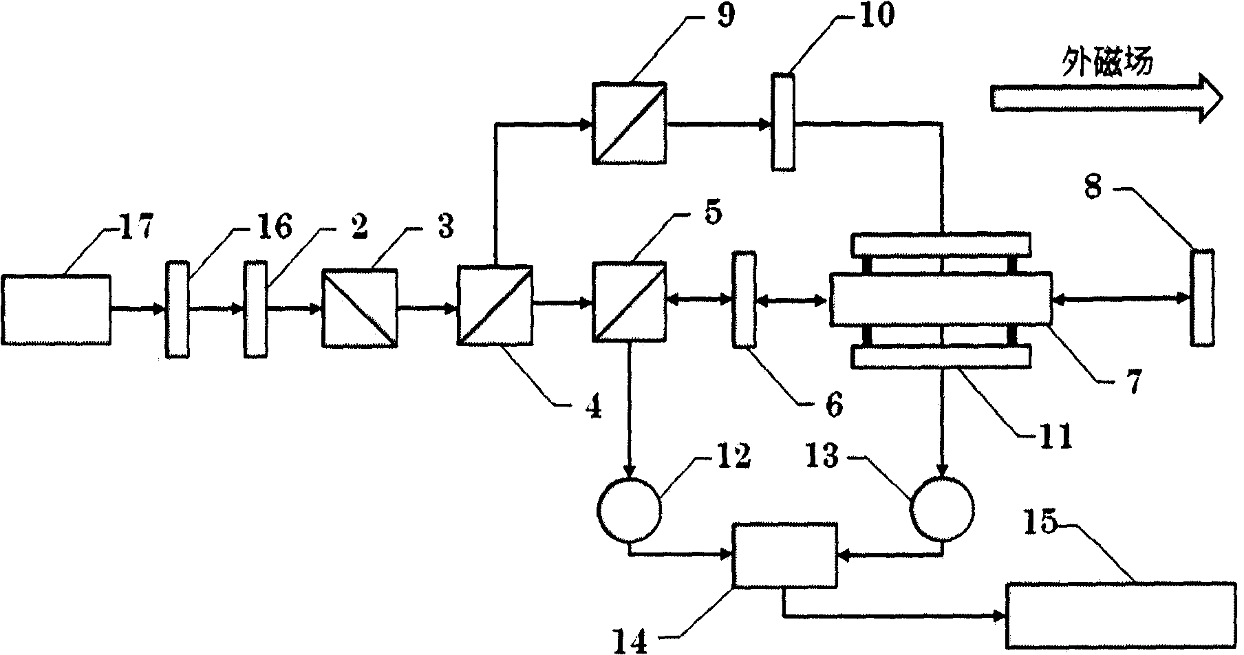
[0018] The optomagnetic double resonance device of the present invention comprises a light source module, an atomic system module, a radio frequency module, a signal detection module and a signal processing module.

[0019] 1. Light source module

[0020] The light source module includes a laser 1, a λ / 2 glass slide 2, a first polarizing beam splitter 3, such as figure 1 As shown, the light beam output by the laser 1 is sequentially incident on the λ / 2 glass plate 2 and th...


PUM


Abstract

The invention belongs to the technical field of optical-magnetic double resonance, and discloses an optical-magnetic double-resonance device, which includes a light source module, an atomic system module, a radio frequency module, a signal detection module, and a signal processing circuit (15). The light source module includes a light source and a polarizer , the atomic system module includes an atomic gas chamber (7), the radio frequency module is fixed on the atomic gas chamber (7), and is used to generate an alternating magnetic field, and the direction of the alternating magnetic field is perpendicular to the axial direction of the atomic gas chamber (7), said The atomic system module also includes a second polarization beam splitter (5), the first λ / 4 glass slide (6) and a mirror (8); the signal detection module includes a beam splitter (4), a third polarization beam splitter Device (9), second λ / 4 slide (10), first photodetector (12), second photodetector (13) and differential circuit (14). The optical-magnetic double resonance device of the invention improves the signal-to-noise ratio of detection signals, and the application of the invention to the optical pump magnetometer can greatly improve the sensitivity and measurement accuracy of the optical pump magnetometer.

Description

technical field [0001] The invention relates to the technical field of optical-magnetic double resonance, in particular to an optical-magnetic double resonance device. Background technique [0002] The optomagnetic double resonance device is currently an important means for studying physical phenomena such as atomic energy level structure, energy level lifetime, and the interaction between atoms and external fields. The device is mainly based on the optomagnetic double resonance phenomenon in atomic physics. When the optical-magnetic double resonance phenomenon occurs, since there is a fixed proportional relationship between the frequency value of the alternating magnetic field in the device and the size of the external magnetic field, the optical-magnetic double resonance device is often used in the field of magnetic field measurement. The optical pump magnetometer made of the device is also one of the most widely used magnetometers at present, especially in national defens...

Claims


Application Information

Patent Timeline
Patent Type & Authority Patents(China)
IPC IPC(8): G01R33/28G01R33/44
Inventor 彭翔郭弘罗斌吴腾公韦
Owner PEKING UNIV
Learn More