Linear sliding block type rotary robot

A rotary motion and slider-type technology, applied in the direction of manipulators, program-controlled manipulators, manufacturing tools, etc., can solve problems such as difficult multi-station production lines, reduce floor space and input costs, expand moving range, and cost-effective high effect

Inactive Publication Date: 2016-06-15
DONGGUAN SUMIDA AUTOMATION CO LTD
View PDF9 Cites 9 Cited by
  • Summary
  • Abstract
  • Description
  • Claims
  • Application Information

AI Technical Summary

Problems solved by technology

However, in the existing linear motor structure, the fixed guide rail seat equipped with permanent magnets is generally used as the stator, and the moving part equipped with the coil is used as the mover. Due to the restraint of the control circuit, the existing linear motor The mover can only slide within the set slide rail range, which is difficult to be used in a multi-station production line and has obvious defects

Method used


Image

  • Linear sliding block type rotary robot
  • Linear sliding block type rotary robot
  • Linear sliding block type rotary robot

Examples


Embodiment Construction

[0020] In order to facilitate the understanding of those skilled in the art, the present invention will be further described below in conjunction with the embodiments and accompanying drawings, and the contents mentioned in the embodiments are not intended to limit the present invention.

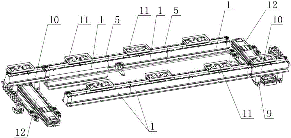
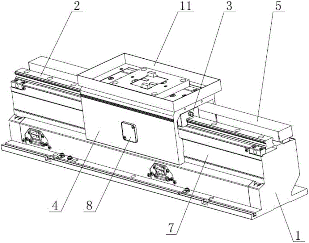
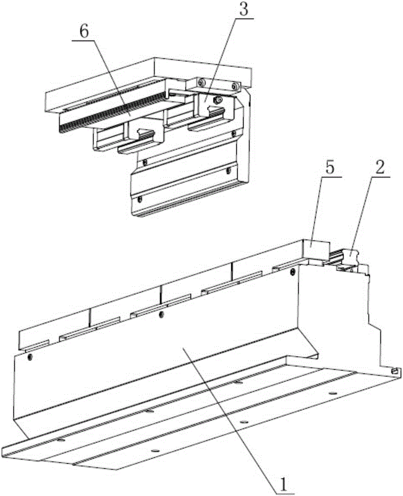
[0021] Such as Figure 1 to Figure 3 Shown is the first embodiment of a linear slider type rotary motion robot of the present invention, which includes at least two fixed guide rail assemblies arranged in parallel, a slide rail 2 installed on the fixed guide rail assembly, and a slider that cooperates with the slide rail 2 3. And the moving part 4 fixedly connected with the slider 3, the fixed guide rail assembly includes at least two fixed guide rail seats 1, and the two adjacent fixed guide rail seats 1 and the slide rails 2 on the fixed guide rail seats 1 are linearly connected; The inside of the moving part 4 is provided with a permanent magnet, and the fixed guide rail seat 1 is equippe...


PUM


Abstract

The invention relates to the technical field of automatic machining equipment, in particular to a linear sliding block type rotary robot which comprises a fixed guide rail assembly, a slide rail arranged on the fixed guide rail assembly, a sliding block matched with the slide rail, and a moving part fixedly connected with the sliding block, wherein two adjacent fixed guide rail seats and slide rails on the fixed guide rail seats are all in linear butt joint; and a movable guide rail seat and a rail change driving mechanism used for driving the movable guide rail seat to laterally move are arranged at the end part of the fixed guide rail assembly. After multiple fixed guide rail seats are subjected to linear butt joint, under the control action of a driving coil, the moving part can move from one fixed guide rail seat to the other guide rail seat, so as to further widen the moving scope of the moving part, and workpiece transportation between two adjacent stations can be realized without special connecting equipment. The linear sliding block type rotary robot is used for column mounting of a production line, thus greatly reducing the occupation area and investment cost of the production line and having relatively high cost performance.

Description

technical field [0001] The invention relates to the technical field of automatic processing equipment, in particular to a linear slider type rotary motion robot. Background technique [0002] With the promotion of machine replacement projects, the traditional assembly line production line is also facing many problems of mechanized transformation, such as the difficulty of long-distance transportation and low transportation accuracy of the conveyor belt, and the use of existing connection equipment is not only expensive , the equipment takes up a lot of space, and the connection effect is difficult to meet the needs of the manufacturer, and the defects are obvious. The linear motor servo system is a power device that directly converts electrical energy into mechanical energy for linear motion. It does not have an intermediate conversion link for a rotating motor, and can effectively overcome the traditional conversion mechanism's large volume, low precision, low efficiency, s...

Claims


Application Information

Patent Timeline
Patent Type & Authority Applications(China)
IPC IPC(8): B25J9/08
CPCB25J9/08
Inventor 李明亮张平良
Owner DONGGUAN SUMIDA AUTOMATION CO LTD
Why Eureka
Try Eureka