Integral grouting and water blocking and plugging device

A water-stopping and grouting technology, which is applied in wellbore/well components, mining equipment, earthwork drilling and mining, etc., can solve the problems of not easy to form accumulation, cement is easily washed away by water, and poor water blocking effect, so as to save cement , Improve the effect of water blocking effect

Inactive Publication Date: 2016-06-15
HENAN POLYTECHNIC UNIV
View PDF5 Cites 7 Cited by
  • Summary
  • Abstract
  • Description
  • Claims
  • Application Information

AI Technical Summary

Problems solved by technology

[0002] Anchor bits play a vital role in the excavation process of mines, railway tunnels and hydropower departments. In the process of drilling rock bolts into rock formations, sometimes the anchor bit drills into the groundwater layer. Once the anchor bit The rod drill drills into the groundwater lay

Method used


Image

  • Integral grouting and water blocking and plugging device
  • Integral grouting and water blocking and plugging device
  • Integral grouting and water blocking and plugging device

Examples


Embodiment 1

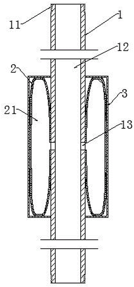
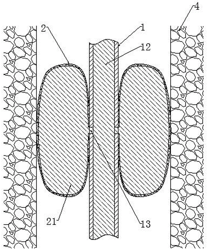
[0018] Embodiment one: see Figure 1-2 , a grouting and water-stopping integrated device, including a bolt 1, the outer circumference of the bolt 1 near both ends is provided with threaded fasteners 11, and the multi-section bolt 1 or the bolt 1 is connected to the anchor drill bit through the threaded fasteners 11 . The anchor rod 1 is provided with a central hole 12 through both ends, the pipe wall of the anchor rod 1 is provided with a side hole 13, the outer circumference of the anchor rod 1 is provided with a destructible protective shell 3, and the protective shell 3 is provided with a bag made of elastic material The bag 2 , the pouch 2 is a pouch made of rubber material, and the pouch chamber 21 of the pouch 2 communicates with the central hole 12 of the anchor rod 1 through the side hole 13 .

[0019] When the bolt is transported, assembled or used normally, the bag 2 is in a contracted state, and the protective shell 3 is used to protect the bag 2 from damage by ext...

Embodiment 2

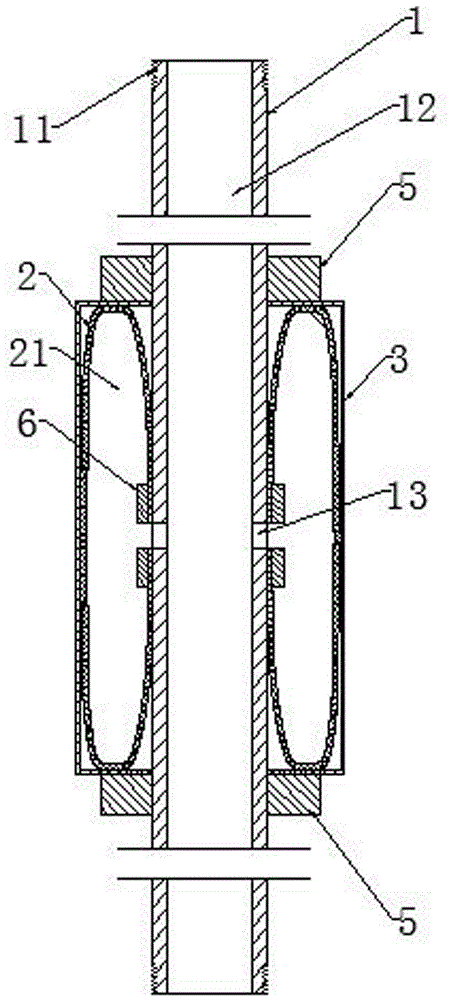
[0020] Embodiment two: see image 3 , Embodiment 2 is basically the same as Embodiment 1, and the similarities will not be described in detail. The difference is that a clip 6 is provided in the pouch cavity 21 of the pouch 2, and the pouch 6 makes the pouch 2 close to the outside of the anchor rod. The peripheral bladder wall is fixed together with the corresponding anchor rod 1 . Blocking platforms 5 are respectively fixed on the outer circumference of the anchor rod 1 at both ends of the protective shell 3 .

[0021] The bladder 2 is fixed on the anchor rod 1 through the clamp 6, and the outer circumference of the anchor rod 1 at both ends of the protective shell 3 is respectively fixed with stoppers 5 to prevent the bladder 2 from sliding axially along the anchor rod 1 when the water pressure is high , to enhance the water blocking effect of the capsule bag 2.

Embodiment 3

[0022] Embodiment three: see image 3 , the third embodiment is basically the same as the second embodiment, and the similarities will not be repeated. The difference is that the anchor rod 1 is provided with two bladder groups along the axial direction, and each bladder group includes a bladder 2, which is located at The protective shell 3 on the outside of the pouch 2 , the hoop 6 arranged in the pouch cavity 21 and the blocks 5 arranged at both ends of the protective shell 3 . The anchor rod 1 is provided with two bladder groups along the axial direction, forming two-stage waterproof layers, and improving the overall water blocking effect of the integrated grouting, water-stopping and water-blocking device.


PUM


Abstract

A grouting, water-stopping and water-blocking integrated device, including an anchor rod, the anchor rod is provided with a central hole passing through both ends, the pipe wall of the anchor rod is provided with side holes, and the outer circumference of the anchor rod is provided with a destructible protective shell, A pouch made of elastic material is arranged inside the protective shell, and the pouch cavity of the pouch communicates with the central hole of the anchor rod through the side hole. The all-in-one device for grouting, water-stopping and water-blocking of the present invention is provided with a capsule bag, if encountering the situation that the anchor bit drills into the groundwater layer, inject cement into the central hole immediately, the cement flows into the capsule cavity of the capsule bag from the side hole, and the capsule When the bag expands, the protective shell will be broken, and the expanded bag will block the drill hole, which can quickly block the water and improve the water blocking effect. Since the cement will not flow out of the bag, a large amount of cement can be saved.

Description

technical field [0001] The invention relates to the technical field of mining equipment, in particular to a grouting, water-stopping and water-blocking integrated device. Background technique [0002] Anchor bits play a vital role in the excavation process of mines, railway tunnels and hydropower departments. In the process of drilling rock bolts into rock formations, sometimes the anchor bit drills into the groundwater layer. Once the anchor bit The rod bit drills into the groundwater layer. Due to the large water storage capacity and high water pressure in the groundwater layer, if the cement is directly injected into the borehole, the cement is easily washed away by water and is not easy to form accumulations. The large amount of cement is used and the water blocking effect is poor. Contents of the invention [0003] In order to solve the above-mentioned technical problem, the present invention proposes a grouting, water-stopping and water-blocking integrated device. ...

Claims


Application Information

Patent Timeline
IPC IPC(8): E21B33/13E21D21/00
CPCE21B33/13E21D21/0026
Inventor 李辉苏勋贾智伟段振伟
Owner HENAN POLYTECHNIC UNIV
Why Eureka
Try Eureka