Feed circuit based on IMPATT diode

A technology of feeding circuit and feeding column, which is applied in the field of radar, can solve problems such as separate consideration, achieve the effect of preventing mutual interference and improving debuggability

Active Publication Date: 2016-06-15
CNGC INST NO 206 OF CHINA ARMS IND GRP
View PDF6 Cites 0 Cited by
  • Summary
  • Abstract
  • Description
  • Claims
  • Application Information

AI Technical Summary

Problems solved by technology

In the literature at home and abroad, there are occasional introductions about the feeding con...

Method used


Image

  • Feed circuit based on IMPATT diode
  • Feed circuit based on IMPATT diode
  • Feed circuit based on IMPATT diode

Examples


Embodiment Construction

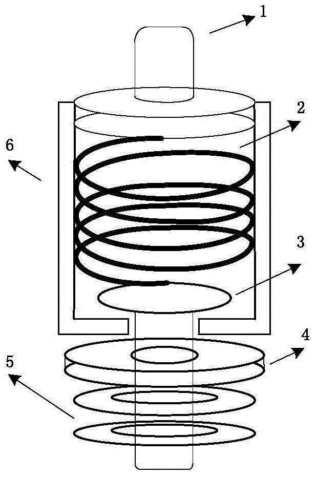
[0026] The overall structure of the feed circuit based on the IMPATT tube is shown as figure 1 As shown, the whole circuit is composed of upper feed column, spring, lower feed column, insulating pad, metal ring and cavity. The upper and lower feed columns are respectively composed of a column and a chassis. The upper column and the external signal are welded to realize the signal feed-in. The lower column is in direct contact with the IMPATT tube to provide a bias signal for the tube. The upper and lower The chassis of the feeding column is relatively placed in the cavity, and a spring is added between the chassis of the upper and lower feeding columns, so that the lower feeding column can generate a corresponding displacement according to the magnitude of the moment. This design, on the one hand, enables the external DC bias signal to be directly fed into the circuit, on the other hand, it can meet the special debugging requirements that require the IMPATT tube to be able t...


PUM


Abstract

The invention relates to the design of a feed circuit based on an IMPATT diode and is mainly used for feed and displacement debugging of a 3 mm microwave device based on the IMPATT diode. Through the unique design of upper and lower feeder pillars and a spring, and by utilizing different displacements of the spring under different moments, displacement debugging of the IMPATT diode is realized; through the introduction of an insulating spacer, short circuit due to contact of the feeder pillars and a cavity can be prevented; and through a quasi coaxial filter structure formed by dual metal rings and the feeder pillars, mutual interference between high-frequency signals and DC bias signals can be prevented. Compared with an existing feed circuit based on the IMPATT diode, the feed circuit based on the IMPATT diode in the invention has the advantages of being easy to assemble, adjustable, resistant to interference and small and the like.

Description

technical field [0001] The invention relates to the technical field of radar, in particular to a design of a feeding circuit of an IMPATT tube, which can be applied to microwave devices such as injection-lock amplifiers and oscillators based on the IMPATT tube. Background technique [0002] In W-band radar transmitters, in order to obtain high-power transmission signals, IMPATT tubes are often used for signal generation and amplification. The avalanche transit time diode is a device based on the negative resistance characteristics generated by the charge (carrier) avalanche multiplication effect and the carrier transit time effect in the semiconductor PN junction. The IMPATT (ImpactAvalanceheTransitTime) tube is based on this kind The mechanism realizes the generation and amplification of the signal. [0003] Due to the special "column" structure of the IMPATT tube, the power supply end is located on the upper part of the tube, and the size of the tube is only It is not p...

Claims


Application Information

Patent Timeline
IPC IPC(8): G01S7/02
CPCG01S7/02
Inventor 张国强张生春周立学饶睿楠杨芳红彭欢雷国忠糜光璞鄢炜森
Owner CNGC INST NO 206 OF CHINA ARMS IND GRP
Why Eureka
Try Eureka