Single-phase AC motor protection circuit, fan and air conditioner

A single-phase AC motor and protection circuit technology, which is applied in the direction of emergency protection circuit devices, electrical components, etc., can solve problems such as stable and reliable operation of unfavorable circuits, temperature rise of K1 and K2, miniaturization of unfavorable circuits, etc.

Active Publication Date: 2016-06-15
GD MIDEA ENVIRONMENT APPLIANCES MFG +1
View PDF5 Cites 8 Cited by
  • Summary
  • Abstract
  • Description
  • Claims
  • Application Information

AI Technical Summary

Problems solved by technology

[0003] 1) When the switch dead time between K1 and K2 (ie: the time from K1 off to K2 on and the time from K2 off to K1 on) is to control the switch of K1 according to the feedback voltage after K2 is disconnected, the advantage is The reverse voltage at both ends of the motor is very low. The disadvantage is that the dead time is too short and it is not easy to control. If the time characteristic difference caused by the characteristic difference of the device may cause a temporary short circuit of K1 and K2, resulting in a temperature rise of K1 and K2 high, even burned
[0004] 2) If the symmetrical PWM self-locking mode is used to drive K1 and K2, the dead time usually needs to be 1-2uS, so the back pressure of the AC motor will be very high, and it is usually necessary to connect a large-capacity capacitor C and resistor in parallel at both ends of the motor R to absorb, called the RC absorption loop, in the RC absorption loop, the capacitance C is too large will lead to high heat generation of the resistor R, increased loss, which is not conducive to the stable and reliable operation of the circuit, and the required volume is also large, which is not conducive to circuit miniaturization
If the dead time is reduced to 0.1-1uS, when there is interference, there may be a temporary short circuit between K1 and K2, and burn K1 and K2

Method used


Image

  • Single-phase AC motor protection circuit, fan and air conditioner
  • Single-phase AC motor protection circuit, fan and air conditioner
  • Single-phase AC motor protection circuit, fan and air conditioner

Examples


Embodiment 3

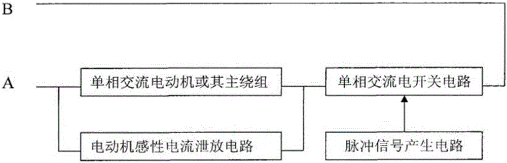
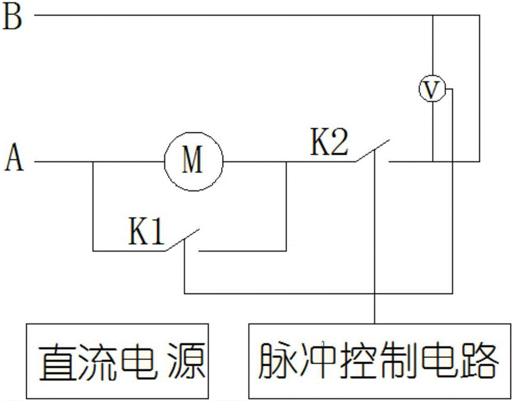
[0048]The main switch circuit in embodiment 3 comprises a rectifier circuit (made up of diodes D3-D6), a DC electronic switch Q3 and a sampling filter circuit, the negative output terminal of the rectifier circuit is connected to the first end of the DC electronic switch Q3, and the positive pole of the rectifier circuit The output end is connected to the second end of the DC electronic switch Q3 through the sampling filter circuit, and the driving end of the DC electronic switch Q3 is connected to the pulse signal output end of the pulse signal generating circuit. Specifically, in Embodiment 3 of the present invention, the DC electronic switch The drive end of Q3 is connected to the pulse signal output end of the pulse signal generating circuit through a resistor; the input end of the sampling filter circuit is connected to the second end of the DC electronic switch Q3, and the output end of the sampling filter circuit is connected to the AD sampling of the pulse signal generat...


PUM


Abstract

The invention relates to a single-phase AC motor protection circuit, a fan and an air conditioner. The circuit comprises an AC motor or a main/secondary winding thereof, a master switch loop, a discharge loop and a pulse signal generation circuit. The AC motor or the main/secondary winding thereof and the master switch loop are connected in series between the null line and the live line of an alternating current; the discharge loop is connected in parallel with the AC motor or the main/secondary winding thereof; and the master switch loop or the discharge loop comprises a first rectification circuit, a first DC electronic switch and a sampling filter circuit. The problems that, in an AC speed regulation circuit, the DC electronic switch in the discharge loop and the DC electronic switch in the master switch loop are very short in dead time, so that when interference or circuit abnormity occurs in the circuit, the DC electronic switch in the discharge loop and the DC electronic switch in the master switch loop have temporary short circuit, which causes large surge current, and the DC electronic switches enter an unstable status and even are burnout due to severe overheat thereof are solved.

Description

technical field [0001] The invention relates to the field of motors, in particular to a single-phase AC motor protection circuit, a fan and an air conditioner. Background technique [0002] At present, the motor speed control circuit has a form such as figure 1 As shown, the basic principle is: through the "single-phase AC switching circuit" PWM modulation, the voltage at both ends of the motor is switched at high speed, so as to adjust the average voltage at both ends of the motor to achieve the purpose of speed regulation. When the "motor inductive current discharge circuit" is a switch circuit, it can be simplified as figure 2 The schematic diagram shown, where K1 represents figure 1 In the "motor inductive current discharge circuit", K2 means figure 1 "Single-phase AC switching circuit" in figure 2 The time control diagram of image 3 As shown, at this time, this speed regulating circuit has the following defects: [0003] 1) When the switch dead time between K1 ...

Claims


Application Information

Patent Timeline
Patent Type & Authority Applications(China)
IPC IPC(8): H02H7/08
CPCH02H7/0833
Inventor 郭新生
Owner GD MIDEA ENVIRONMENT APPLIANCES MFG
Why Eureka
Try Eureka