
A Real-time Error Compensation Method for Atomic Clocks

An error compensation and atomic clock technology, applied in the field of real-time error compensation for atomic clocks to reduce frequency offsets, can solve the problems of limited environmental control, can no longer produce significant effects, cannot be used as a reference or secondary frequency standard, etc. , to achieve the effect of improving frequency stability and reducing frequency shift uncertainty

Active Publication Date: 2018-08-14
SHANGHAI INST OF OPTICS & FINE MECHANICS CHINESE ACAD OF SCI
View PDF4 Cites 0 Cited by
  • Summary
  • Abstract
  • Description
  • Claims
  • Application Information

AI Technical Summary

Problems solved by technology

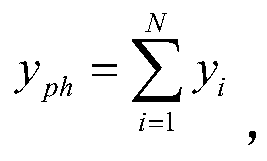
[0004] The traditional method of reducing the frequency shift of atomic clocks mainly relies on suppressing a certain physical effect to deal with the time-dependent noise, usually through active or passive ways to effectively reduce x i ups and downs, and then according to x i The statistical characteristics of the statistical characteristics to get its contribution to the uncertainty, the statistical characteristics mentioned here are processed according to the standard deviation, in fact, the noise characteristics of various effects present different noise characteristics (such as white noise, random walk, etc.), these effects Finally, it is reflected by the frequency output of the atomic frequency standard. Some effects lead to long-term frequency drift of some atomic frequency standards, which cannot be used as a reference or secondary frequency standard.
[0005] The traditional atomic clock feeds the detected frequency error signal directly to the local oscillator. The method to reduce the frequency shift can only rely on improving the performance of the physical system and more precise control of the atom and its environment, regardless of the performance of the physical system. The improvement of the environment and the control of the environment are limited, and can no longer produce significant effects

Method used


Image

  • A Real-time Error Compensation Method for Atomic Clocks
  • A Real-time Error Compensation Method for Atomic Clocks
  • A Real-time Error Compensation Method for Atomic Clocks

Examples


Embodiment Construction

[0026] The present invention will be further described below in conjunction with the accompanying drawings and embodiments.

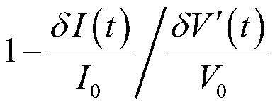
[0027] We performed experimental verification on the atomic fountain system. The second-order Zeeman effect is selected as the compensation object, and its noise is amplified so that its contribution to the fountain frequency standard uncertainty is much greater than other effects, and its correlation function is detected to test the change of the fountain frequency standard uncertainty before and after noise compensation.

[0028] In the present embodiment, atomic clock (b) adopts fountain atomic clock (h), figure 2 The resistor (j) and the acquisition part of the control card (k) in the figure 1 The first detector (c) in , figure 2 The detector (i) in is equivalent to figure 1 In the second detector (d), the specific steps of implementing the real-time error compensation method are as follows:

[0029] ① Turn on the fountain atomic clock (h), an...


PUM


Abstract

The invention discloses a method for carrying out real-time error compensation on an atomic clock to reduce frequency deviation. Through monitoring an environmental noise variable, an error signal which is affected by the environmental noise variable is compensated and is fed back to a local oscillator in real time to inhibit the effect of the environmental noise, the limitations to atoms and environmental fluctuation control thereof are broken, the frequency uncertainty of the atomic clock is remarkably reduced, and meanwhile, the stability of the atomic clock is improved.

Description

technical field [0001] The invention belongs to a real-time error compensation method, in particular to a method for reducing frequency offset by performing real-time error compensation on an atomic clock. Background technique [0002] Atomic clocks are time-measuring instruments that can be viewed as a combination of a local oscillator and a frequency discrimination physical system. Its working principle is that the microwave signal output by the local oscillator is multiplied and then input to the microwave cavity of the atomic clock to interact with the atoms. The atomic system acts as a frequency discriminator. After the voltage signal, the local oscillator is locked by servo control, and the other frequency signal output by the local oscillator is used as the atomic frequency standard signal, and the accurate time signal is obtained through correction and processing. The fractional frequency offset measured by the frequency discrimination system can be expressed as: y ...

Claims


Application Information

Patent Timeline
Patent Type & Authority Patents(China)
IPC IPC(8): H03L7/26G04F5/14
CPCG04F5/14H03L7/26
Inventor 陈婷婷魏荣董日昌王文丽邹凡王育竹
Owner SHANGHAI INST OF OPTICS & FINE MECHANICS CHINESE ACAD OF SCI
Learn More