Device for monitoring abnormal working state of numerical control milling cutter and monitoring method of device
A technology of working status and monitoring devices, which is applied in the direction of manufacturing tools, metal processing equipment, measuring/indicating equipment, etc., can solve the problems of online and real-time monitoring and control of tool wear and damage, and achieve manpower saving, accurate measurement accuracy, Avoid the effect of damage
- Summary
- Abstract
- Description
- Claims
- Application Information
AI Technical Summary
Problems solved by technology
Method used
Image

Examples
specific Embodiment approach 1
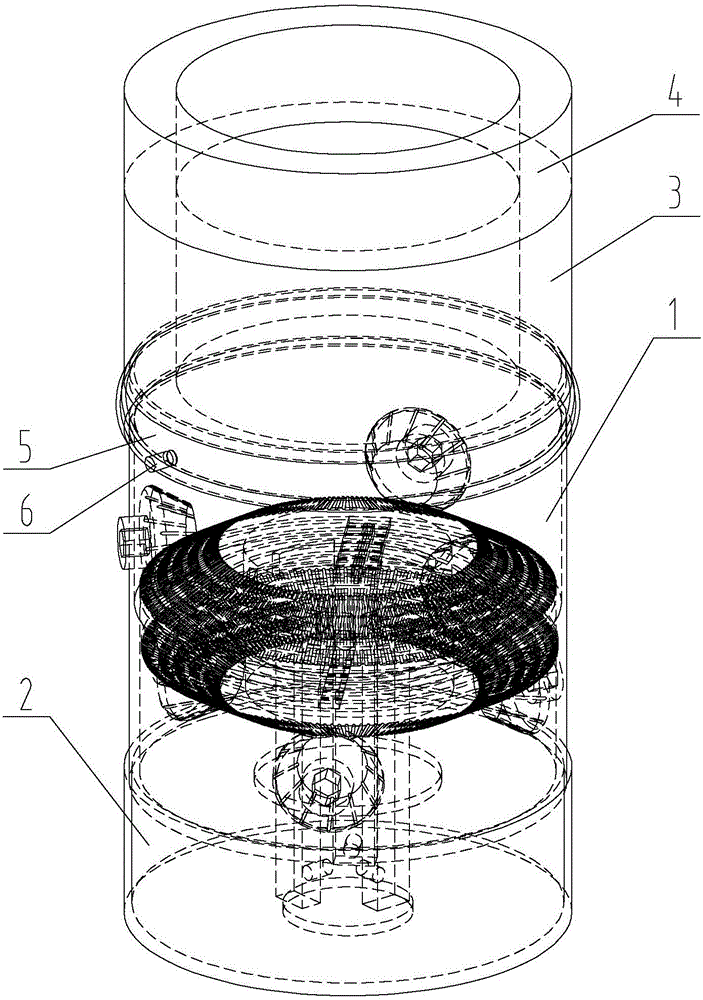
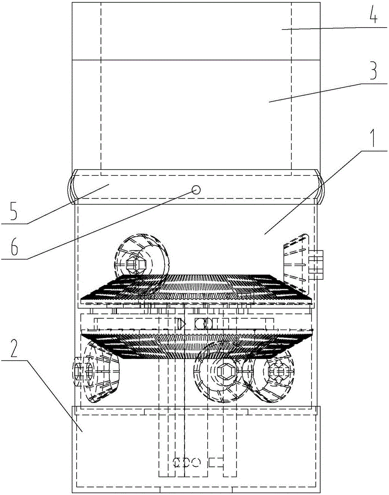
[0037] Specific implementation mode one: combine Figure 1 to Figure 15 Describe this embodiment, the monitoring device of a kind of numerical control milling tool abnormal working state described in this embodiment comprises measuring head 1, observation cover 2, collecting and transmitting mechanism 3, permanent magnetic sucker 4 and control panel, and observing cover 2 is arranged on the measuring head 1, the upper end of the measuring head 1 is provided with a permanent magnetic chuck 4, a collection and launching mechanism 3 is arranged between the measuring head 1 and the permanent magnetic chuck 4, and a positioning through hole 2-1 is arranged on the lower end surface of the observation cover 2, and the measurement The head 1 includes an outer casing 1-1, a positioning mechanism and an adjustment mechanism, the positioning mechanism and the adjustment mechanism are respectively arranged inside the outer casing 1-1, and the adjustment mechanism is provided with an eddy c...
specific Embodiment approach 2
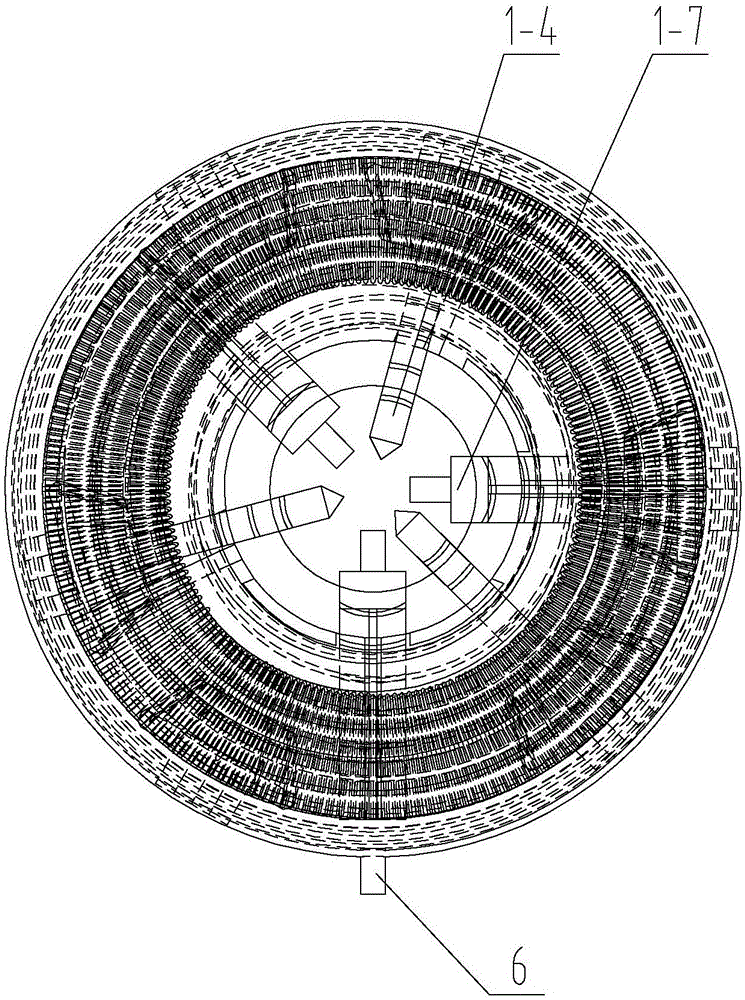
[0038] Specific implementation mode two: combination Figure 1 to Figure 14 To illustrate this embodiment, a partition 1-1-1 is provided inside the outer casing 1-1 of this embodiment, and three first limiting grooves 1-1-1 are respectively provided on the partition 1-1-1 along the radial direction. 2 and three second limiting grooves 1-1-3, the middle part of the partition plate 1-1-1 is provided with a middle through hole 1-1-4, and the positioning mechanism includes a positioning large bevel gear 1-2, a group of positioning small Bevel gear 1-3 and three positioning columns 1-4, the adjustment mechanism includes adjusting large bevel gear 1-5, a set of adjusting small bevel gear 1-6 and three claws 1-7, positioning large bevel gear 1-2 The large bevel gear 1-5 is symmetrically arranged on both ends of the partition 1-1-1, and the end faces of the large bevel gear 1-2 and the large bevel gear 1-5 are set inward respectively, and the large bevel gear 1-5 is positioned inward....
specific Embodiment approach 3
[0039] Specific implementation mode three: combination Figure 1 to Figure 4 Describe this embodiment, the monitoring device of a kind of CNC milling tool abnormal working state described in this embodiment also includes joint bearing 5, and joint bearing 5 is arranged between collecting and transmitting mechanism 3 and measuring head 1, and the upper end of measuring head 1 passes through lock Tightening screw 6 is connected with joint bearing 5. The undisclosed technical features in this embodiment are the same as those in the first or second specific embodiment.
[0040] In this embodiment, the measuring head 1 is connected with the collection and launching mechanism 3 through the joint bearing 5 to prevent the unevenness of the upper surface adsorbed by the permanent magnetic chuck 4 from affecting the positioning of the measuring head 1, thereby ensuring the measurement accuracy.
PUM
 Abstract
Description
Claims
Application Information
 - R&D
- Intellectual Property
- Life Sciences
- Materials
- Tech Scout
- Unparalleled Data Quality
- Higher Quality Content
- 60% Fewer Hallucinations
Browse by: Latest US Patents, China's latest patents, Technical Efficacy Thesaurus, Application Domain, Technology Topic, Popular Technical Reports.
© 2025 PatSnap. All rights reserved.Legal|Privacy policy|Modern Slavery Act Transparency Statement|Sitemap|About US| Contact US: help@patsnap.com