
Accelerated flow energy dissipation and energy feedback device of iron concentrate slurry pipeline and control method of device

An energy feedback, iron concentrate technology, applied in pipeline systems, mechanical equipment, gas/liquid distribution and storage, etc., can solve the problems of wasted energy, energy consumption is not well recovered, uneconomical, etc.

Active Publication Date: 2016-06-22
KUNMING UNIV OF SCI & TECH
View PDF5 Cites 2 Cited by
  • Summary
  • Abstract
  • Description
  • Claims
  • Application Information

AI Technical Summary

Problems solved by technology

This method is an ideal method for energy dissipation, but this method wastes most of the energy, and the energy of energy dissipation is not recovered well, which is an uneconomical way
[0006] In the long-distance pipeline slurry transportation project, the pipeline works 24 hours under normal working conditions, and the accelerated flow energy dissipation of the pipeline is carried out 24 hours without interruption. The energy dissipation of the traditional method for many years wastes a lot of energy.

Method used


Image

  • Accelerated flow energy dissipation and energy feedback device of iron concentrate slurry pipeline and control method of device
  • Accelerated flow energy dissipation and energy feedback device of iron concentrate slurry pipeline and control method of device
  • Accelerated flow energy dissipation and energy feedback device of iron concentrate slurry pipeline and control method of device

Examples


Embodiment 1

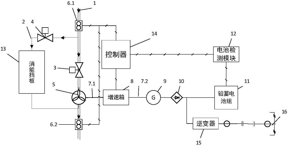
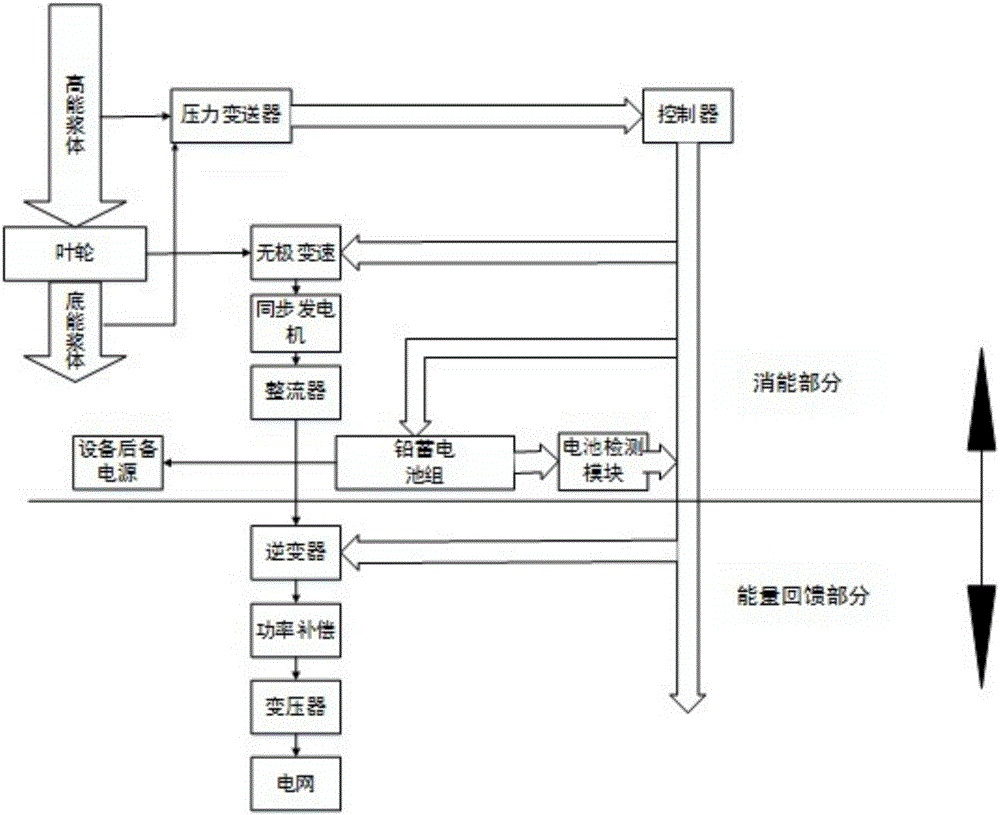
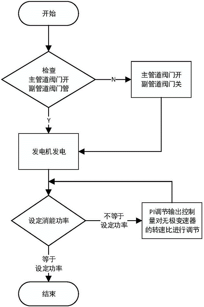
[0034] Embodiment 1: as Figure 1-5 As shown, an iron concentrate slurry pipeline acceleration flow energy dissipation and energy feedback device includes main pipeline 1, auxiliary pipeline 2, electric knife switch valve I3, electric knife switch valve II4, centrifugal pump 5, and pressure transmitter I6. 1. Pressure transmitter Ⅱ6.2, coupling Ⅰ7.1, coupling Ⅱ7.2, gearbox 8, synchronous generator 9, rectifier group 10, battery group 11, battery detection module 12, energy dissipation block Board 13, controller 14, inverter 15, enterprise internal grid 16;

[0035] The auxiliary pipeline 2 is installed next to the main pipeline 1, and the energy dissipation baffle 13 is installed on the auxiliary pipeline 2. The control input line of the energy dissipation baffle 13 is connected to the controller 14, the electric knife puller valve I3, the electric knife puller valve II4 The opening and closing control lines of the pressure transmitter are connected to the controller 14, the ...

Embodiment 2

[0042] Embodiment 2: as Figure 1-5 As shown, an iron concentrate slurry pipeline acceleration flow energy dissipation and energy feedback device includes main pipeline 1, auxiliary pipeline 2, electric knife switch valve I3, electric knife switch valve II4, centrifugal pump 5, and pressure transmitter I6. 1. Pressure transmitter Ⅱ6.2, coupling Ⅰ7.1, coupling Ⅱ7.2, gearbox 8, synchronous generator 9, rectifier group 10, battery group 11, battery detection module 12, energy dissipation block Board 13, controller 14, inverter 15, enterprise internal grid 16;

[0043] The auxiliary pipeline 2 is installed next to the main pipeline 1, and the energy dissipation baffle 13 is installed on the auxiliary pipeline 2. The control input line of the energy dissipation baffle 13 is connected to the controller 14, the electric knife puller valve I3, the electric knife puller valve II4 The opening and closing control lines of the pressure transmitter are connected to the controller 14, the ...

Embodiment 3

[0049] Embodiment 3: as Figure 1-5 As shown, according to the actual transportation situation of the iron concentrate slurry pipeline (diameter 100mm) operated by a certain company, every 100m of pressure head can generate 23KW energy and recover electric energy of 23ηKW (efficiency factor η). The system has 500m of excess slurry pressure head, can generate 115KW of energy, and generates power of 115ηKW. Centrifugal pump 5 selects 80DFZ-520A type slurry pump (efficiency 70%) produced by Shijiazhuang Dongfanghong Industrial Pump Factory. The controller 14 adopts Micrologic1400PLC and 1762-IQ16, 1762-IF2OF2 expansion I / O modules of American Rockwell Company. Electric knife switch valve I3 and electric knife switch valve II4 can choose DZW10 series knife switch valve manufactured by Yangzhou Xinneng Electric Power Equipment Co., Ltd. The speed-up box (8) can be selected from the planetary speed-up box produced by Shanghai Jiyou Automation Technology Co., Ltd., in continuous op...


PUM


Abstract

The invention relates to an accelerated flow energy dissipation and energy feedback device of an iron concentrate slurry pipeline and a control method of the device, and belongs to the technical field of fluid accelerated flow energy dissipation and energy feedback equipment. An auxiliary pipeline is mounted beside a main pipeline, an energy dissipation baffle is mounted on the auxiliary pipeline, and the energy dissipation baffle, an electric knife pulling valve I, an electric knife pulling valve II, a pressure transmitter I, a pressure transmitter II and a gearbox are connected with a controller, and a centrifugal pump is mounted on the main pipeline; the centrifugal pump is connected with the gearbox through a coupler I, and the gearbox is connected with a synchronous generator through a coupler II; the electric energy output end of the synchronous generator is connected with the rectifying input end of a rectifier stack, and the output of the rectifier stack is connected with a charging terminal of a storage battery; the input end of a battery detection module is connected with the output end of the storage battery, and the output end of the battery detection module is connected into the controller; and the rectifier stack is connected with an inverter, and the inverter outputs redundant electric energy to an enterprise inner power network in a grid-connection manner. According to the device and method, long-distance accelerated flow energy dissipation and energy feedback of the iron concentrate slurry pipeline can be achieved.

Description

technical field [0001] The invention relates to an accelerated flow energy dissipation and energy feedback device for an iron concentrate slurry pipeline and a control method thereof, and belongs to the technical field of fluid accelerated flow energy dissipation energy feedback equipment. Background technique [0002] Long-distance slurry pipeline transportation systems are often laid in rugged mountainous areas. Due to the difference in elevation between the starting point and the end point or the difference in specific gravity between the slurry and water during batch transportation, it will cause a common problem in the hydraulic analysis of slurry, that is, the accelerated flow of slurry pipeline. The generation of this accelerated flow is actually caused by excess energy, which is usually consumed automatically by forming a dissatisfied flow similar to an open channel when the pipe is full. The speed of this accelerated flow may exceed the flow rate of normal full pip...

Claims


Application Information

Patent Timeline
IPC IPC(8): F17D1/14F17D1/20F17D3/01F17D5/02
CPCF17D1/14F17D1/20F17D3/01F17D5/02
Inventor 吴建德周唯王晓东范玉刚黄国勇邹金慧冷婷婷张馨予李富玉熊新冯早
Owner KUNMING UNIV OF SCI & TECH
Learn More