Medium-temperature solar heat collector

A technology of solar heat collectors and high temperature resistance, which is applied in the directions of solar heat collectors, solar heat collector heat insulation, solar heat collector parts, etc., and can solve the problem of reducing the range of solar heat utilization, low efficiency for commercial use, High operating costs and other issues, to achieve the effect of improving heat collection efficiency, fast heat start, and high heat collection efficiency

Inactive Publication Date: 2016-06-22
BEIJING BORIMING ENERGY TECH
View PDF3 Cites 0 Cited by
  • Summary
  • Abstract
  • Description
  • Claims
  • Application Information

AI Technical Summary

Problems solved by technology

[0002] With the improvement of people's awareness of environmental protection and energy saving, solar energy, as a new type of renewable clean energy, has been widely used in people's daily life, but the existing vacuum tube heat collector can only provide hot water at about 70 °C, which greatly The range of solar heat utilization is reduced, but the current U-shaped tube collectors, metal-glass sealed heat pipe collectors, and trough heat collectors that can provide medium-temperature heat sources are high in cost, high in operating costs, and low in efficiency and cannot be invested. commercial use

Method used


Image

  • Medium-temperature solar heat collector
  • Medium-temperature solar heat collector
  • Medium-temperature solar heat collector

Examples


Embodiment Construction

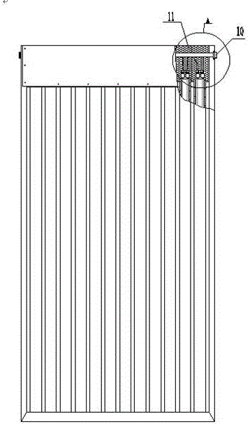
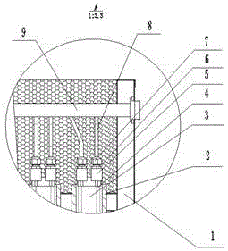
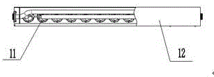
[0011] First, weld the connecting joint (5) to the upper end of the curved metal runner (3), apply the high temperature resistant heat-conducting adhesive (4) on the upper part of the curved metal runner (3), and insert the curved metal runner (3) into the vacuum tube (2) Inside, the communication joint (5) is located outside the vacuum tube at the upper end of the curved metal flow channel (3). Put the gasket (6) into the upper part of the communication joint (5), put the vacuum tube (2) into the frame (1), and place the manifold (8) Insert the sodium joint (7) Screw the sodium joint (7) into the upper part of the communication joint (5), insert the manifold (8) into the lower part of the main flow channel (9) and weld it, and connect the joint (11 ) into the two ends of the main flow channel (9) and welded, fix the lower end cover (14) on the upper bottom of the frame (1), fill the insulation material (12) in the vacuum tube (2) and on the lower end cover (14) ,) Fix the upp...


PUM


Abstract

The invention relates to a medium-temperature solar heat collector. The medium-temperature solar heat collector consists of a curved surface metal runner, a communicating joint, high-temperature resistant heat conducting glue, a vacuum pipe, an insulation material, a gasket, a copper joint, a manifold, a main pipe runner, connecting joints, a frame, an upper end cover and the lower end cover, and is characterized in that the high-temperature resistant heat conducting glue is positioned at the lower part of the inner wall of the vacuum pipe and the upper part of the curved surface metal runner; the curved surface metal runner is in the vacuum pipe; a metal runner blind plate is positioned at the lower end of the curved surface metal runner; the communicating joint is positioned out of the vacuum pipe at the upper end of the curved surface metal runner; the gasket is positioned at the upper part of the communicating joint; the copper joint is positioned at the upper part of the communicating joint; the manifold is positioned at the upper part of the copper joint and the lower part of the main pipe runner; the main pipe runner is positioned at the upper part of the manifold; the connecting joints are positioned at two ends of the main pipe runner; the frame is fixedly surrounded by the vacuum pipe out of the vacuum pipe; the lower end cover is positioned at the bottom end of the upper part of the frame; the upper end cover is positioned at the upper end of the upper part of the frame; and the insulation material is below the curved surface metal runner in the vacuum pipe and in the upper end cover and the lower end cover of the frame.

Description

technical field [0001] The invention relates to a medium-temperature solar heat collector, which uses a solar vacuum tube as a heat-absorbing element to install a curved metal flow channel in the vacuum tube, and fills the metal flow channel with a high-efficiency high-temperature-resistant heat-conducting medium. When the vacuum tube absorbs solar heat, it is quickly introduced into the metal flow channel to heat the metal. The medium in the flow channel is exported when the temperature of the medium in the metal flow channel reaches a medium temperature, and a medium temperature heat source is obtained, which belongs to the field of solar energy manufacturing. Background technique [0002] With the improvement of people's awareness of environmental protection and energy saving, solar energy, as a new type of renewable clean energy, has been widely used in people's daily life, but the existing vacuum tube heat collector can only provide hot water at about 70 ℃, which greatly...

Claims


Application Information

Patent Timeline
Patent Type & Authority Applications(China)
IPC IPC(8): F24J2/05F24J2/24F24J2/34F24J2/51F24J2/46F24S10/40F24S10/70
CPCF24S10/40F24S10/70F24S60/00F24S80/00F24S80/60F24S2025/601Y02E10/44
Inventor 张清海沈俊清李坡曲佃超
Owner BEIJING BORIMING ENERGY TECH
Why Eureka
Try Eureka