
A layout method for directional x-ray detection vertical transillumination

A technology of vertical transillumination and arrangement method, applied in the direction of using radiation for material analysis, etc., can solve the problems of increasing transillumination time, prolonging detection time, rework, etc., to increase the available area, increase the utilization area, and reduce production. cost effect

Active Publication Date: 2020-03-17
CHANGZHI QINGHUA MACHINERY FACTORY +1
View PDF6 Cites 0 Cited by
  • Summary
  • Abstract
  • Description
  • Claims
  • Application Information

AI Technical Summary

Problems solved by technology

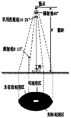
[0005] a. Due to the limitation that the center of the transillumination beam should generally point vertically to the center of the transillumination area and should coincide with the normal of the workpiece surface, only a single transillumination arrangement can be used;
[0006] b. The irradiation angle (also known as the crack detection angle) limits the irradiation in the entire cone area, resulting in the unutilized area and part of the available area not being actually utilized, and the rays in this area exist as harmful rays;
[0007] c. Using a large focal length layout, the allowable transillumination length can be increased linearly, but the transillumination time needs to be increased by a square multiple, resulting in a longer detection time;
[0008] d. Flowing water transillumination operation causes fluctuations in the consistency of layout parameters, transillumination parameters, darkroom processing parameters and process parameters, resulting in large fluctuations in the quality of negatives and even rework
[0009] That is, according to the above background technology, it is difficult to efficiently complete the directional X-ray detection operation

Method used


Image

  • A layout method for directional x-ray detection vertical transillumination
  • A layout method for directional x-ray detection vertical transillumination
  • A layout method for directional x-ray detection vertical transillumination

Examples


Embodiment Construction

[0030] The invention discloses an arrangement method for directional X-ray detection of vertical transillumination. Those skilled in the art can learn from the content of this article and appropriately improve the process parameters to realize it. In particular, it should be pointed out that all similar replacements and modifications are obvious to those skilled in the art, and they are all considered to be included in the present invention. The products described in the present invention have been described through preferred embodiments, and relevant personnel can obviously make changes or appropriate changes and combinations to the compositions and applications described herein without departing from the content, spirit and scope of the present invention to achieve and Apply the technology of the present invention.

[0031] The present invention will be further described below in conjunction with specific examples.

[0032] The present invention has no limitation on the spe...


PUM


Abstract

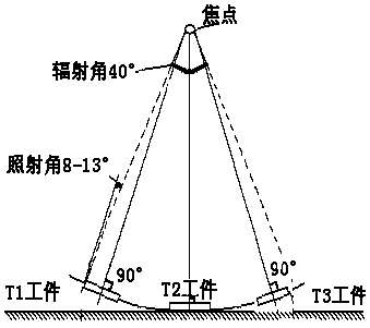
The invention relates to a method for detecting vertical transillumination by orientation X rays. The scheme provided by the invention comprises the following steps: step 1: selecting an orientation X ray machine and workpieces to be detected; step 2: mounting the X ray machine, and radiating X ray beams generated by the orientation X ray machine into a space at a 40-degree tapered angle; forming a conical transillumination field by taking an illumination distribution focal length as a radius, wherein a transillumination region center of each workpiece to be detected is tangent to a spherical surface to form a certain beam which is vertical to the transillumination region center of each workpiece to be detected, the only beam is vertical to the workpiece after the transillumination region center is tangent to any determined point of the spherical surface, and a usable region of the conical transillumination field is formed by a single workpiece plane and a ray beam with an irradiation angle which is not more than 13 degrees; processing a plurality of workpieces by adopting the method to finally form one ray source and a plurality of conical transillumination fields; step 3: carrying out illumination distribution on the plurality of conical transillumination fields by taking a vertical distance as the focal length so that the ray beams completely cover all illumination distribution workpieces; and vertically calibrating, and carrying out an illumination distribution and transillumination process. With the adoption of the method, orientation X ray detection work can be efficiently finished.

Description

technical field [0001] The invention relates to an arrangement method for directional X-ray detection transillumination, in particular to a non-destructive testing field applied to aerospace, aviation, special equipment and the like. Background technique [0002] Since the X beam generated by the directional ray machine is radiated into the space at a cone angle of 40°, the workpiece (or weld) is arranged perpendicular to the central beam, and the layout plane and the beam space form an X-ray conical transillumination field, such as figure 1 shown. [0003] According to the requirements of the industry standard for directional ray detection, the transillumination layout requires that the center of the ray beam be vertically directed to the center of the transillumination area, and the irradiation angle does not exceed 13°. In the conical transillumination field, a small conical transillumination field with a cone angle of 26° is in compliance. The area of ​​quality requirem...

Claims


Application Information

Patent Timeline
Patent Type & Authority Patents(China)
IPC IPC(8): G01N23/02
CPCG01N23/02
Inventor 刘小明韩壮壮赵振武程建成上官洛奎柳育红董辉李海燕王云飞边晶晶段鑫
Owner CHANGZHI QINGHUA MACHINERY FACTORY
Learn More