A path programming method for a plane redundancy robot to avoid obstacles and avoid singularities

A technology for path planning and robotics, applied in two-dimensional position/channel control and other directions, and can solve problems such as

Inactive Publication Date: 2016-06-22
HARBIN INST OF TECH
View PDF1 Cites 21 Cited by
  • Summary
  • Abstract
  • Description
  • Claims
  • Application Information

AI Technical Summary

Problems solved by technology

At present, in the field of planar redundant robot motion control, there is no report on the path planning method for simultaneous obstacle avoidance and singularity avoidance.

Method used


Image

  • A path programming method for a plane redundancy robot to avoid obstacles and avoid singularities
  • A path programming method for a plane redundancy robot to avoid obstacles and avoid singularities
  • A path programming method for a plane redundancy robot to avoid obstacles and avoid singularities

Examples


specific Embodiment approach 1

[0111] DETAILED DESCRIPTION One. The method for path planning for obstacle avoidance and singularity avoidance of a planar redundant robot described in this embodiment is performed according to the following steps:

[0112] The method of the present invention involves two simultaneous processes:

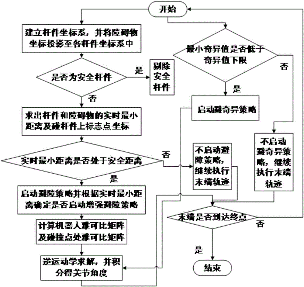
[0113] Process 1: The path planning steps for obstacle avoidance are as follows:

[0114] Step 1: Establish the coordinate system of each member, and project the coordinates of each obstacle to the coordinate system of each member;

[0115] Step 2: Judge whether the rod is a safe rod;

[0116] Step 2. One: If the rod is a safety rod, then the rod will be rejected without any treatment;

[0117] Step 2. Two: If the rod is not a safety rod, go to step three;

[0118] Step 3: Find the real-time minimum distance between the connecting rod and the obstacle and the coordinates of the mark points on each rod;

[0119] Step 4: Judge whether the real-time minimum distance is at a safe distance;

[0120] St...

specific Embodiment approach 2

[0139] Specific implementation manner 2. This implementation manner is a further description of a planar redundant robot obstacle avoidance and singularity avoidance path planning method described in specific implementation manner 1. The specific process of step one is:

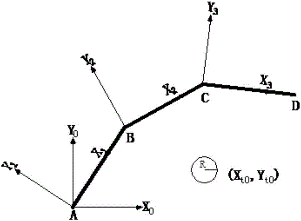
[0140] The connecting rod of the present invention is composed of rod 1, rod 2 and rod 3;

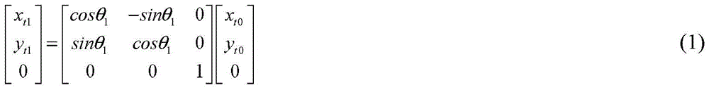
[0141] The position of the center of the known obstacle in the coordinate system {0} (x t0 ,y t0 ), the connecting rod section is a square with side length a, and the obstacle radius is R. According to the rotation matrix of the coordinate system {1} relative to the coordinate system {0}, the position of the obstacle center in the coordinate system {1} is obtained (x t1 ,y t1 ),which is

[0142] x t 1 y t 1 0 = cosθ 1 - sinθ 1 0 sinθ 1 cosθ 1 0 0 0 1 x t 0 y t 0 0

[0143] By...

specific Embodiment approach 3

[0145] Embodiment 3 This embodiment is a further explanation of a planar redundant robot obstacle avoidance and singularity avoidance path planning method described in Embodiment 1 or 2. The specific process of step 2 is:

[0146] If (x t1 ,y t1 )Satisfy

[0147] | y A 1 - y t 1 | ≥ R + a x t 1 ≥ x B 1 + R

[0148] or | y A 1 - y t 1 | ≥ R + a x A 1 - R ≥ x t 1

[0149] Bar 1 is a safety bar, so there is no need to calculate the distance between it and the obstacle;

[0150] If (x t1 ,y t1 )Satisfy

[0151] | y A 1 - y t 1 | ≤ R + a x A 1 - R ≤ x t 1 ≤ x B 1 + R - - - ( 4 )

[0152] Where x A1 , Y A1 Is the position coordinate of point A on the member 1 in the coordinate system {1}, x B1 Is the abscissa of the posit...


PUM


Abstract

A path programming method for a plane redundancy robot to avoid obstacles and avoid singularities relates to the field of robot motion control, and especially relates to a plane redundancy robot to avoid obstacles and avoid singularities. The invention aims to solve problems that risk of hurting working personnel by existing plane redundancy robots exists in a cooperation process and the speed of joints will exceed a robot allowance scope when the end of the robot moves to a singular position. The method of the invention is carried out according to the following steps: the method of the invention relates to threads which are carried out simultaneously: the first thread relates to several steps of path programming to avoid obstacles; and the second thread relates to various steps of path programming to avoid singularities. The method of the invention ca simultaneously complete the path programming method of obstacle avoidance and singularity avoidance, so that in a cooperation process, collaborator avoidance can be completed, and avoiding of singular configuration of the robot can also be realized to reduce risks of man-machine cooperation and raise the assembling quality. The method of the invention can be applied to the field of robot motion control.

Description

Technical field [0001] The invention relates to the field of robot motion control, in particular to a path planning method for obstacle avoidance and singularity avoidance of a planar redundant robot. Background technique [0002] With the miniaturization and precision of electronic products, traditional robot automated assembly cannot well complete some complex and refined assembly tasks, and the complete manual completion of the assembly tasks of such products will greatly increase the labor intensity of the staff, thus Affect the assembly quality of the product. At present, foundry manufacturers have begun to introduce planar robots as auxiliary equipment for high-speed production lines to assist staff in the assembly of electronic products, reduce staff labor intensity and improve assembly quality. Assisting workers to complete assembly tasks in a narrow space such as an assembly line greatly increases the probability of human-machine collision. This not only poses a great ...

Claims


Application Information

Patent Timeline
Patent Type & Authority Applications(China)
IPC IPC(8): G05D1/02
CPCG05D1/02
Inventor 刘玉斌戴骞张赫赵杰李戈
Owner HARBIN INST OF TECH
Why Eureka
Try Eureka