Magnetic pressure coupling resonant converter

A coupled resonance, converter technology, applied in transformer/inductor components, transformer/inductor coil/winding/connection, conversion of AC power input to DC power output, etc., can solve the trouble of circuit design and converter conversion efficiency. reduce problems, to achieve the effect of cost saving, excitation current reduction, and power loss reduction

Inactive Publication Date: 2016-06-22
ANSHAN JILI OPTOELECTRONICS TECH CO LTD
View PDF6 Cites 0 Cited by
  • Summary
  • Abstract
  • Description
  • Claims
  • Application Information

AI Technical Summary

Problems solved by technology

[0003] The traditional resonant converter uses two separate components, the transformer and the resonant inductor, which are limited by space and location in layout and installation, which brings a lot of trouble to the circuit design, and the power consumed by the components separately causes the converter to Reduced conversion efficiency

Method used


Image

  • Magnetic pressure coupling resonant converter
  • Magnetic pressure coupling resonant converter
  • Magnetic pressure coupling resonant converter

Examples


Embodiment Construction

[0030] The technical content of the present invention will be further described in detail below in conjunction with the accompanying drawings.

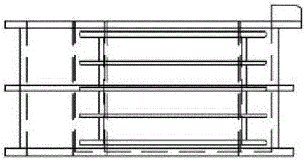
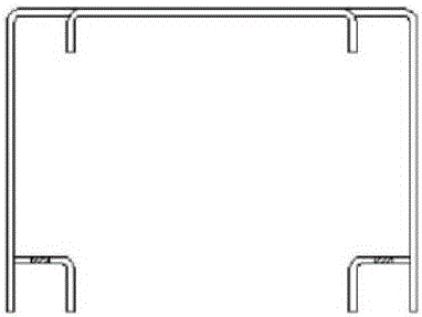
[0031] A magnetic-pressure coupled resonant converter, comprising a converter bobbin, an inductance core 1, a transformer core 2, a coupling magnetic circuit, and a clamp kit, and the primary coil 3 and the secondary coil 4 are respectively wound on the primary coil bobbin and the secondary on the bobbin, such as Picture 1-1 , Figure 1-2 , diagram 2-1 , Figure 2-2 , Figure 3-1 , Figure 3-2 As shown, the converter bobbin is composed of the secondary bobbin embedded in the primary bobbin, such as Pic 4-1 , Figure 4-2 As shown, the transformer core 2 is inserted into the position of the secondary coil bobbin, Figure 5-1 , Figure 5-2 As shown, the inductance core 1 is inserted into the corresponding position of the primary coil bobbin, and finally used Figure 6-1 , Figure 6-2 The clips shown secure the assembled trans...


PUM


Abstract

The invention relates to a magnetic pressure coupling resonant converter, which includes a converter skeleton, an inductor magnetic core, a transformer magnetic core, and a coupling magnetic circuit, and is characterized in that two different magnetic cores, the inductor magnetic core and the transformer magnetic core, are assembled in the same On the converter frame, the primary windings are wound on all the middle columns of the two types of magnetic cores, and the secondary windings are wound on the middle columns of the transformer magnetic core, and the alternating current is connected to realize magnetic pressure coupling to form a coupled magnetic circuit, and then the card The hoop assembly is fixed, and the advantage is that the conversion efficiency of the resonant converter is greatly improved, and the size is small, the structure is simple, the work is stable, and it is convenient for industrialized mass production.

Description

technical field [0001] The invention relates to the technical field of power electronics, in particular to a magnetic pressure coupling resonant converter. Background technique [0002] In the prior art, both LC and LLC resonant converters are well known and widely used in laser, medical, environmental protection, excitation, electronics and other fields, and are also an indispensable part of many industrial equipment. [0003] The traditional resonant converter uses two separate components, the transformer and the resonant inductor, which are limited by space and location in layout and installation, which brings a lot of trouble to the circuit design, and the power consumed by the components separately causes the converter to The conversion efficiency is reduced. Contents of the invention [0004] The invention provides a magnetic pressure coupling resonant converter, which integrates the converter and the resonant inductance converter into one body by means of magnetic ...

Claims


Application Information

Patent Timeline
Patent Type & Authority Applications(China)
IPC IPC(8): H02M7/537H01F27/30
CPCH02M7/537H01F27/306
Inventor 张琦孙钢吕卫
Owner ANSHAN JILI OPTOELECTRONICS TECH CO LTD
Why Eureka
Try Eureka