Magnetizing inductance variable LLC resonant transformer

A technology of resonant transformer and magnetizing inductance, applied in variable transformers, inductors, transformers, etc., can solve the problems of low light-load efficiency, non-adjustable magnetizing inductance, and inability to achieve light-load efficiency.

Active Publication Date: 2018-10-16
HUNAN INSTITUTE OF ENGINEERING
View PDF8 Cites 6 Cited by
  • Summary
  • Abstract
  • Description
  • Claims
  • Application Information

AI Technical Summary

Problems solved by technology

However, the LLC resonant converter also has its inherent defects: the output voltage regulation range is narrow, and the light load efficiency is low, which is a difficult problem that must be solved in the application of electric vehicle battery charging
The document "Light-LoadEfficiency Improvement Strategy for LLC Resonant Converter Utilizing a Step-Gap Transformer" gives a step-gap transformer solution to improve the loss of LLC resonant converter at light load, but the magnetic Core processing is difficult and costs increase
The invention patent "LLC transformer and switching power supply" (patent number: 201611048791.0) realizes adjustable leakage inductance through a special winding structure, but the excitation inductance is not adjustable
The utility model patent "A LLC Transformer" (patent number: 201620955772.5) provides a transformer winding method to reduce the skin effect and proximity effect, but it cannot achieve the improvement of light load efficiency
The scheme described in the above literature cannot better solve the different requirements for K of the LLC resonant converter under heavy load and light load

Method used


Image

  • Magnetizing inductance variable LLC resonant transformer
  • Magnetizing inductance variable LLC resonant transformer
  • Magnetizing inductance variable LLC resonant transformer

Examples


Embodiment Construction

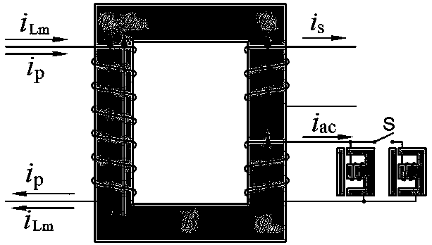
[0056] like figure 1 As shown, an embodiment of the present invention consists of a power magnetic core without an air gap and three windings on it to form the main body of the transformer, and two AC inductors with air gaps are used as AC loads for the main body of the transformer, two of which have Whether the AC inductors of the air gap are connected individually or simultaneously is controlled by the switch 5. When the load is heavy, the two AC inductors are connected at the same time. When the load is light, the switch 5 is disconnected, and only one AC inductor is connected.

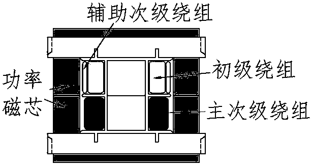
[0057] like figure 2 Shown is a schematic diagram of the magnetic flux inside the main power core of the transformer. There are 3 windings on the power core, the primary is on the left, and the secondary and auxiliary secondary windings are on the right. primary current i p and the secondary current i s Magnetic flux established in the core respectively and cancel each other out, the excit...


PUM


Abstract

The invention discloses a magnetizing inductance variable LLC resonant transformer. The magnetizing inductance variable LLC resonant transformer comprises a primary winding 1, a main secondary winding2, an auxiliary secondary winding 3, a power magnetic core 4, a switch 5, and two alternating current inductors 6 and 7 with air gaps. The two terminals of the alternating current inductor 6 with airgap are respectively connected with the two terminals of the auxiliary secondary winding 3. One terminal of the alternating current inductor 7 with air gap is connected in parallel with the alternating current inductor 6 with air gap through the switch 5. Compared with a traditional LLC transformer, the gain adjustment range of the LLC resonant converter can be wide during heavy load, and the primary loop current is small during light load, so that the output characteristic and light load efficiency of the LLC resonant converter are effectively improved.

Description

technical field [0001] The invention relates to an LLC resonant transformer, which is especially suitable for an LLC resonant converter with a wide range of load variation, can realize the improvement of light load efficiency, and is especially suitable for charging electric vehicle batteries. Background technique [0002] The LLC resonant converter is one of the most commonly used circuit topologies in switching power supplies at present, because the main power switching device can realize zero-voltage (ZVS) turn-on, and the secondary rectifier diode can realize zero-current turn-off (ZCS). The characteristics of output filter inductance and resonant cavity current waveform close to sine wave make it have the advantages of small electromagnetic interference, high peak efficiency and high power density. However, the LLC resonant converter also has its inherent defects: narrow output voltage regulation range and low light load efficiency, which is a difficult problem that mus...

Claims


Application Information

Patent Timeline
Patent Type & Authority Applications(China)
IPC IPC(8): H02M3/335H01F29/00H01F27/24H01F27/28
CPCH01F27/24H01F27/28H01F29/00H02M3/3353H02M1/0058Y02B70/10
Inventor 赵振兴浣喜明
Owner HUNAN INSTITUTE OF ENGINEERING
Why Eureka
Try Eureka