Three-hole transonic speed pressure probe

A transonic and transonic flow technology, which is applied in the measurement of fluid pressure, fluid velocity measurement, velocity/acceleration/impact measurement, etc., can solve the problems of total pressure loss, requirements, and less use, and achieve the reduction of total pressure loss in the flow field Small, not easy to blow and bend, with little effect

Active Publication Date: 2016-06-29
BEIHANG UNIV
View PDF2 Cites 70 Cited by
  • Summary
  • Abstract
  • Description
  • Claims
  • Application Information

AI Technical Summary

Problems solved by technology

Although traditional pressure probes can be used for the measurement of supersonic airflow, the effect is not ideal
When measuring supersonic airflow or approaching the speed of sound, there are two main problems in using these probes. One is that shock waves will appear in front of the probe during supersonic measurement, and there is a total pressure loss, which also has a great impact on the flow field. When the incoming flow velocity is relatively high, the resistance to the probe is relatively large, and there is a high requirement for the strength of the probe.
Although traditional pressure probes can be used in supersonic flow fields, they are rarely used

Method used


Image

  • Three-hole transonic speed pressure probe
  • Three-hole transonic speed pressure probe
  • Three-hole transonic speed pressure probe

Examples


Embodiment Construction

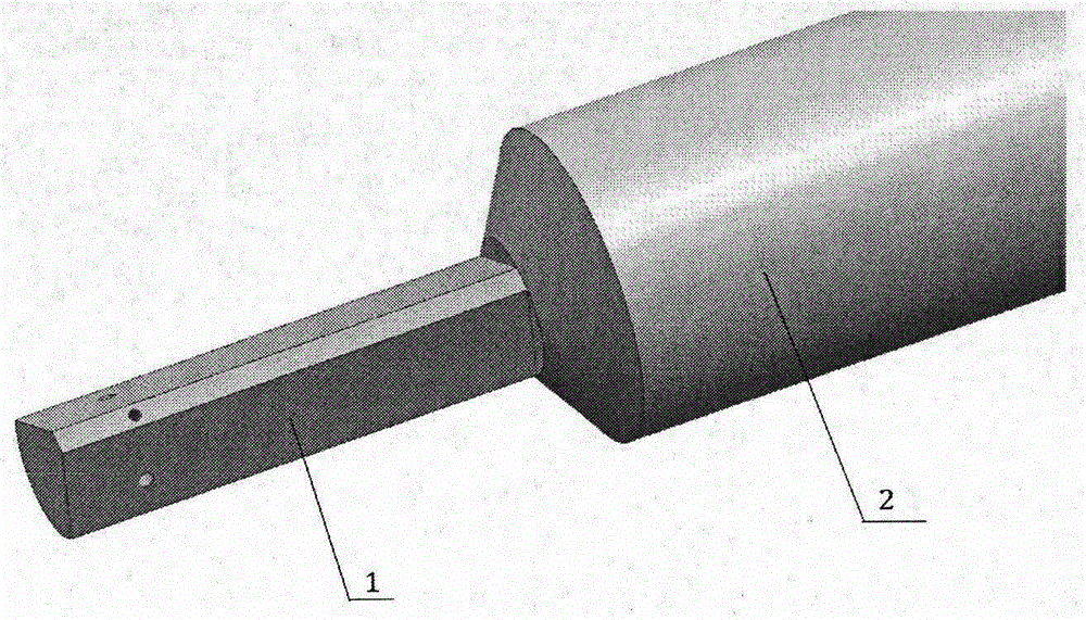
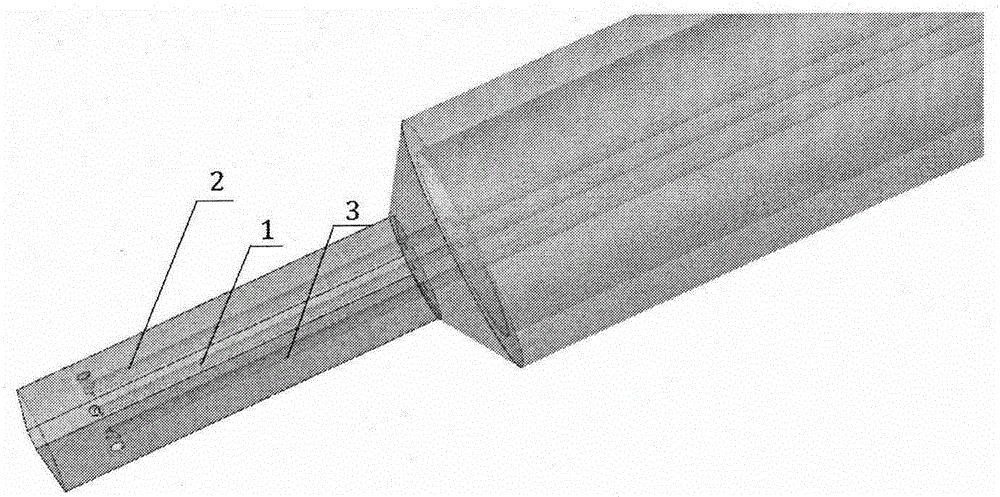
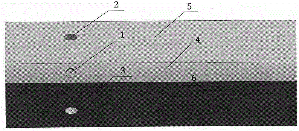
[0013] Such as figure 1 As shown, the probe probe is installed on the probe support rod, and the probe is made into a shape where the wedge and the circular table are connected, and the front and back of the wedge are arc surfaces. Open a pressure introduction hole on the front arc of the probe, and open a pressure introduction hole at the same position on the left and right sides of the probe wedge, as image 3 shown. The pressure of the three holes is led out by the pressure pipe along the probe rod, such as figure 2 shown. In this way, the aerodynamic resistance of the probe is not only small, which ensures the firmness and reliability of the probe, but also weakens the shock wave intensity in front of the probe and reduces the influence of the probe on the flow field.


PUM


Abstract

The invention discloses a three-hole transonic speed pressure probe. As a pneumatic technology develops, a transonic speed air flow appears more and more frequently, for instance, many air flows in an aeroengine reach a transonic speed state, so these transonic speed flow fields need to be measured and analyzed during development of engine components. Conventionally, the transonic speed flow fields are measured respectively by use of a total pressure probe and a direction probe so that total pressure and air flow directions can be obtained. When a flow speed reaches a transonic speed, the probes are under great resistance, and the probes are blown bent easily. When the flow speed reaches an ultrasonic speed, due to the existence of shock waves, there is large total pressure loss, and the influences exerted by the probes on the flow fields are quite large. Though these conventional probes can be used in an ultrasonic air flow, the influences exerted by the probes on the flow fields cannot be neglected, and the requirement for the strength of the probes is quite high. The novel three-hole transonic speed pressure probe provided by the invention is used for measuring the transonic speed flow fields. By use of the probe provided by the invention, the intensity of the shock waves in front of the probe can be weakened during measurement, the influences exerted by the probe on the flow fields are reduced, air-flow total pressure, static pressure, a Mach number and an air-flow deflection angle can be measured simultaneously, the resistance acting on the probe can be effectively reduced, and the firmness and reliability of the probe are guaranteed.

Description

technical field [0001] After the three-hole transonic pressure probe is calibrated to obtain the calibration curve, the experimentally measured three-hole pressure can accurately obtain the total pressure, static pressure, Mach number and airflow deflection angle of the flow field according to the calibration curve. The three-hole transonic probe is not only suitable for subsonic speed, but also can be used in supersonic speed. It is suitable for the measurement of the transonic flow field in the engine, and it is also suitable for other transonic flow fields. Background technique [0002] There are many methods for collecting flow field information, such as PIV, LDV, hotline, probe and so on. Probes are widely used due to their simple structure, strong and durable, easy to operate and so on. Traditional pressure probes such as three-hole probes, five-hole probes, seven-hole probes, etc. are widely used in the measurement of flow fields. With the development of aero-engine...

Claims


Application Information

Patent Timeline
Patent Type & Authority Applications(China)
IPC IPC(8): G01L27/00G01P5/175G01P21/00
Inventor 马宏伟修跃飞马融
Owner BEIHANG UNIV
Why Eureka
Try Eureka