
Creep test device and control system thereof

A technology of creep test and controller, which is applied in the field of compression creep test of similar materials, can solve the problem that the loading accuracy of small tonnage axial load cannot be guaranteed, the stability and continuity of axial load cannot be guaranteed, and the deformation measurement cannot be satisfied. Precision requirements and other issues, to achieve the effect of improving space utilization, stable work, and reasonable space design

Inactive Publication Date: 2016-06-29
SHANDONG UNIV
View PDF11 Cites 14 Cited by
  • Summary
  • Abstract
  • Description
  • Claims
  • Application Information

AI Technical Summary

Problems solved by technology

[0005] 1. The traditional creep testing machine uses a displacement meter to measure the deformation of the specimen. Due to the limited measurement accuracy of the displacement meter, the deformation measurement of the specimen is inaccurate and cannot meet the accuracy requirements for deformation measurement in the creep test of the specimen.
[0006] 2. When the axial load of large tonnage can be provided, the loading accuracy of small tonnage axial load cannot be guaranteed; when the loading accuracy of small tonnage axial load can be guaranteed, sufficient large tonnage axial load cannot be provided
[0007] 3. The loading force on the specimen cannot be constant, and there is a large deviation between the axial load value provided by the test device and the set constant value during the test
The stability and continuity of the axial load cannot be guaranteed during the long-term loading process, and the verticality or magnitude of the load is prone to change

Method used


Image

  • Creep test device and control system thereof
  • Creep test device and control system thereof
  • Creep test device and control system thereof

Examples


Embodiment 1

[0044] The present invention will be further described below in conjunction with the accompanying drawings.

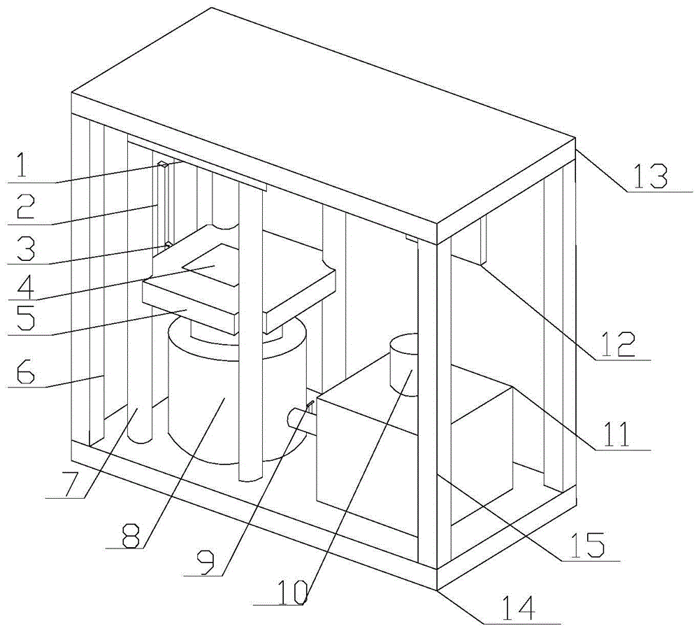
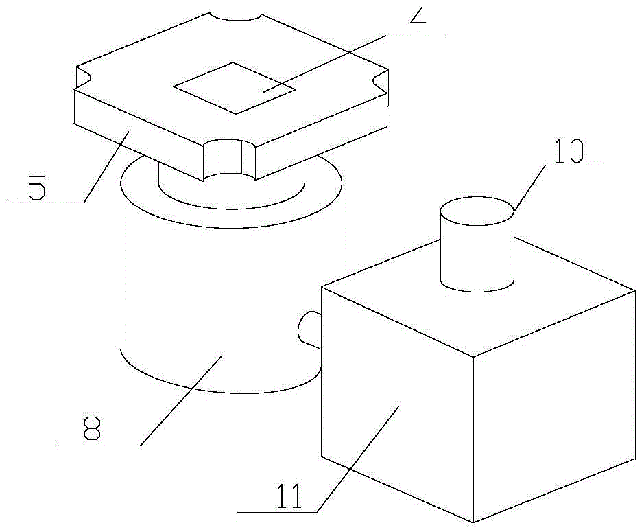
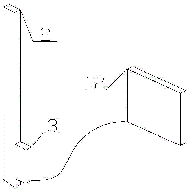
[0045] In the figure, a creep test device. Including the control system, which is composed of scale grating 2 and grating reading head 3. The scale grating 2 is fixed vertically on the left side of the test bench, and the grating reading head 3 is fixed on the lower pressure plate 5. During the installation process, ensure that the ruler body is parallel to the guide rail , its parallelism meets the installation requirements (the parallelism cannot exceed 0.1mm, and the maximum parallelism cannot exceed 0.15mm). During the creep process of the specimen, the grating reading head 3 moves with the lower pressure plate 5 to record the displacement change. The grating reading The head 3 is connected with the controller 12 through cables, and records relevant data in real time.

[0046] The loading system is composed of a hydraulic oil tank 11, an electric pump 10, and a hy...

Embodiment 2

[0050] When a hydraulic jack is used, the hydraulic jack can also be set above the test piece and fixedly connected with the top cover of the reaction force frame, so that the hydraulic jack can apply load from top to bottom.


PUM


Abstract

The invention relates to a creep test device and a control system thereof. The test device comprises a counter-force frame, a loading system and a controller; the loading system used for performing axial pressurization on a test piece is arranged in the counter-force frame and performs axial loading on the test piece through a movable pressure bearing part; a scaleplate optical grating used for testing deformation of the test piece is arranged on the counter-force frame in the vertical direction, and the movable pressure bearing part is provided with an optical grating reading head working in cooperation with the scaleplate optical grating; the loading system, a pressure sensor and the optical grating reading head are all connected with the controller; the controller controls loads exerted by the loading system, and the deformation amount of the test piece is acquired through the optical grating reading head. The creep test device and the control system thereof improve loading precision and displacement measurement precision in a creep test, it is guaranteed that pressure in the rock creep process is a constant value, automatic pressurization is achieved, work is stable, and testing precision is high.

Description

technical field [0001] The invention relates to a creep test device and its control system, which can be used not only for the compression creep test of rocks, but also for the compression creep test of similar materials. Background technique [0002] In the process of tunnel construction, most of the instability and damage of the surrounding rock are related to the creep characteristics of the rock. In order to ensure the safety and long-term stability of the tunnel construction, the creep characteristics of the rock must be considered. Geomechanical model test is a method to study the physical and mechanical properties of rock medium. Similar materials play a decisive role in the success of the model test. Similar materials are used to simulate the normal stress state, ultimate load and failure form of rock. It is widely used in soil engineering research, and the key to the success of model tests lies in the similarity between similar materials and real rocks. Using the m...

Claims


Application Information

Patent Timeline
Patent Type & Authority Applications(China)
IPC IPC(8): G01N3/12
CPCG01N3/12
Inventor 杨为民王康王浩杨昕
Owner SHANDONG UNIV
Learn More