
Method for detecting flaw through infrared thermography

An infrared thermal imaging and defect technology, applied in the direction of material defect testing, etc., can solve the problem of extraction without considering the size of the defect, without giving the three-dimensional image or cross-sectional view of the tomographic reconstruction, and achieve high-quality results.

Inactive Publication Date: 2016-06-29
COMAC +1
View PDF2 Cites 19 Cited by
  • Summary
  • Abstract
  • Description
  • Claims
  • Application Information

AI Technical Summary

Problems solved by technology

The Chinese invention patent "Reconstruction method of infrared thermal wave detection tomographic image" (public number CN1696674A) also studies the depth-based infrared detection tomographic reconstruction method, but only gives the plane tomographic images of flat-bottomed blind hole defects at different depths , does not give the tomographically reconstructed stereoscopic image or its profile, and the detection object is only defects with different depths, and does not consider the problem of defect size extraction, and depth and size are two aspects of defect image reconstruction

Method used


Image

  • Method for detecting flaw through infrared thermography
  • Method for detecting flaw through infrared thermography
  • Method for detecting flaw through infrared thermography

Examples


Embodiment Construction

[0028] The present invention will be described in further detail below in conjunction with the accompanying drawings and specific examples.

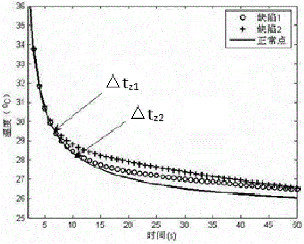
[0029] Step 1: Perform thermal excitation on the test piece, and simultaneously use an infrared thermal imager to obtain time-series detection thermal images of the surface of the test piece before, during and after the excitation for a period of time.

[0030] Specifically, in the infrared thermal image detection, a lamp or hot air is used to thermally excite the tested piece, while the infrared thermal imager records the time-series detection thermal images of the surface of the tested piece on the same side of the tested piece. see figure 1 , figure 1 pairs with different depth Z 1 ,Z 2 The test piece of the flat-bottomed blind hole defect is tested, and the time-series detection thermal image of the normal area and the defect area is obtained. The curve of the temperature change with time. According to the heat conduction model, ...


PUM


Abstract

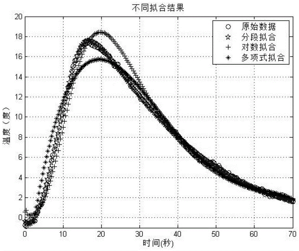
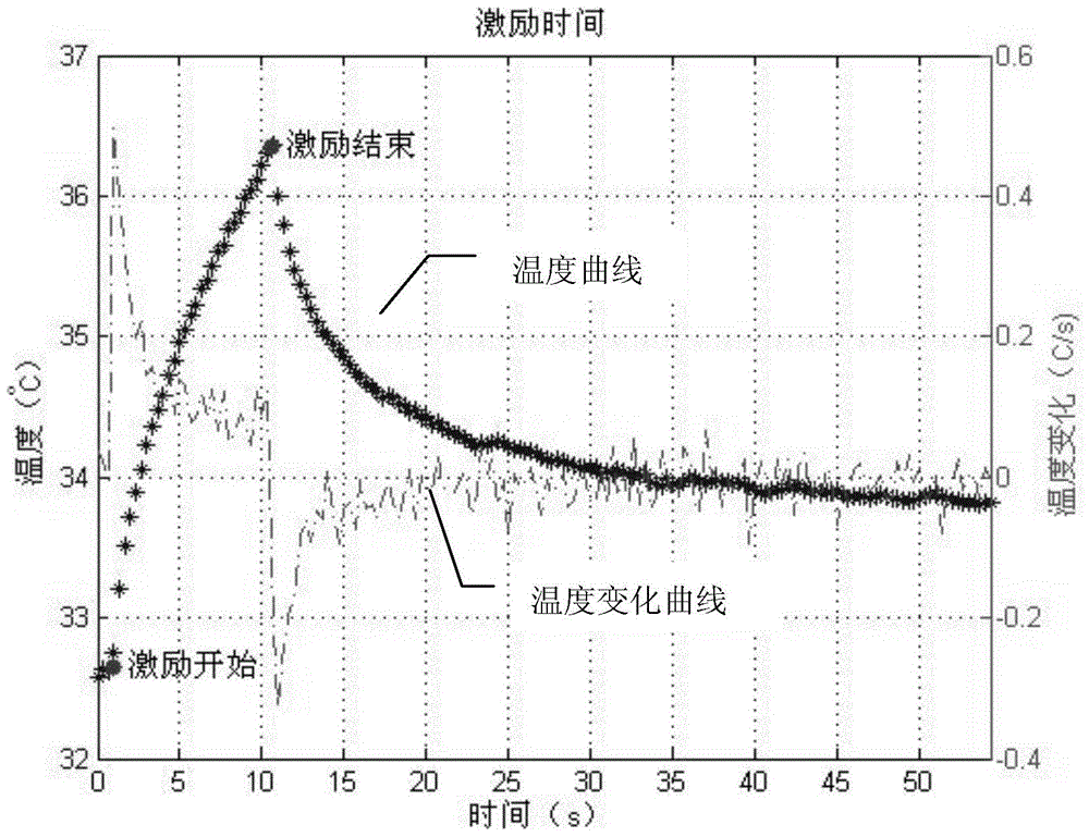
The invention provides a method for detecting a flaw through infrared thermography. The method comprises the following steps that thermal excitation is performed on a detected test piece, time sequence detection thermal images of the surface of the detected test piece in a period of time before, in and after excitation are acquired through a thermal infrared imager; temperature fitting is performed on the temperature rising stage and the temperature lowering stage; the average temperature is derived to take a maximum value to determine an excitation starting time point and an excitation finishing time point in detection to build time references for analyzing a relationship between the flaw and the time; second derivatives of the average temperature are solved to take an extreme value to determine the precise time when a temperature difference occurs; after excitation is finished, the area size of the flaw is detected, and a threshold value coefficient in a half maximum contrast width method is determined to range from 0.5 to 0.7; a contour surface is constructed in time sequence according to a same image grey value, and a three-dimensional flaw reconstruction result is acquired by adopting a projection method. According to the method, high-precision flaw projection reconstruction can be achieved.

Description

technical field [0001] The invention relates to a method for detecting defects by infrared thermal imaging. Background technique [0002] Infrared thermal imaging non-destructive testing technology is a new non-destructive testing technology that has gradually matured with the development of thermal imaging technology. Infrared thermal image detection is to receive the infrared radiation emitted by the object and display it in the form of a thermal image with an infrared thermal imager. When an object has defects, its thermal conductivity is significantly different from that of the object material itself. Under a certain thermal excitation, the defect will affect the heat conduction, resulting in abnormal surface temperature distribution. The infrared thermal imaging camera and other sensing devices are used to measure the surface temperature change of the inspected structure, and then the characteristics of the internal defect are obtained through analysis and processing t...

Claims


Application Information

Patent Timeline
IPC IPC(8): G01N25/72
CPCG01N25/72
Inventor 刘卫平张冬梅刘奎黄姿禹周晖于光肖鹏张继敏
Owner COMAC
Learn More