
Grounding electrode wire fault monitoring method based on high frequency current injection

A technology for high-frequency current and lead wire faults, applied in the directions of measuring electricity, measuring electrical variables, measuring resistance/reactance/impedance, etc., can solve the problem of low reliability, achieve the effect of improving reliability and reducing the difficulty of setting

Active Publication Date: 2016-06-29
STATE GRID SICHUAN ELECTRIC POWER CORP ELECTRIC POWER RES INST +1
View PDF4 Cites 13 Cited by
  • Summary
  • Abstract
  • Description
  • Claims
  • Application Information

AI Technical Summary

Problems solved by technology

[0005] What the present invention aims to solve is the problem of low reliability in monitoring UHVDC ground electrode lead wire faults based on the injection method in the prior art

Method used


Image

  • Grounding electrode wire fault monitoring method based on high frequency current injection
  • Grounding electrode wire fault monitoring method based on high frequency current injection
  • Grounding electrode wire fault monitoring method based on high frequency current injection

Examples


Embodiment

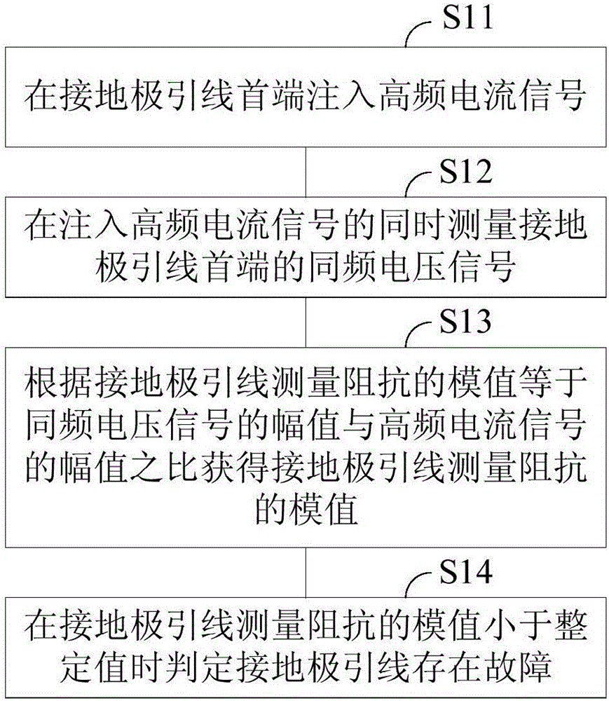
[0036] figure 1 It is a schematic flow chart of a grounding electrode lead fault monitoring method based on high-frequency current injection according to an embodiment of the present invention, and the high-frequency current injection-based grounding electrode lead fault monitoring method includes:

[0037] Step S11 , injecting a high-frequency current signal at the first end of the ground electrode lead. Specifically, a high-frequency current signal is injected into the head end of the ground electrode lead through a signal injection device in the converter station. The amplitude of the high-frequency current signal can be set according to actual needs, and the frequency of the high-frequency current signal is determined according to the length of the ground electrode lead wire and the parameters of the ground electrode lead wire. In this embodiment, the amplitude of the injected high-frequency current is set to 0.15A. The ground electrode leads of UHV DC transmission proje...


PUM


Abstract

The invention discloses a grounding electrode wire fault monitoring method based on high frequency current injection. The method comprises the steps of: injecting high frequency current signals to a head end of a grounding electrode wire, wherein the frequency of the high frequency current signals meets an inequation shown in the specification, lT is the length of the grounding electrode wire, fin is the frequency of the high frequency current signals, L1 is the inductance of per unit length of the grounding electrode wire, and C1 is the capacitance of per unit length of the grounding electrode wire; measuring co-frequency voltage signals of the head end of the grounding electrode wire while injecting the high frequency current signals; according to the fact that the module value of grounding electrode wire measuring impedance is equal to the ratio of the amplitude of the co-frequency voltage signals to the amplitude of the high frequency current signals, obtaining the module value of grounding electrode wire measuring impedance; and if the module value of grounding electrode wire measuring impedance is smaller than a setting value, determining that the grounding electrode wire has a fault. According to the invention, the frequency selection range of the injected high frequency current signals is given, and in the range, the law that the grounding electrode wire measuring impedance is monotonously increased with the increasing of the fault distance is ensured.

Description

technical field [0001] The invention relates to the technical field of ultra-high voltage direct current transmission line monitoring, in particular to a method for monitoring ground electrode lead wire faults based on high-frequency current injection. Background technique [0002] UHVDC transmission technology has the advantages of large transmission capacity, long transmission distance, and strong control performance, and plays a pivotal role in the long-distance transmission of electric energy and the interconnection of regional power grids. The grounding electrode is an important part of the UHV DC transmission system, and it mainly plays the role of providing a return path to the earth and establishing a system voltage reference point. With the continuous construction and operation of UHVDC transmission projects, the selection of the pole location of the grounding pole is becoming more and more difficult. At the same time, considering the influence of DC bias on the equ...

Claims


Application Information

Patent Timeline
Patent Type & Authority Applications(China)
IPC IPC(8): G01R31/00G01R27/08
CPCG01R27/08G01R31/00
Inventor 滕予非焦在滨李小鹏王鱼甄威
Owner STATE GRID SICHUAN ELECTRIC POWER CORP ELECTRIC POWER RES INST
Learn More