Clock device based on timestamp and counters and achieving method thereof

A technology of a clock device and an implementation method, applied in the direction of generating/distributing signals, etc., can solve the problems of bus read delay, increase hardware cost, lack of chips, etc., and achieve the effect of accurate and reliable reading and high real-time performance.

Inactive Publication Date: 2016-06-29
STATE GRID INTELLIGENCE TECH CO LTD
View PDF4 Cites 7 Cited by
  • Summary
  • Abstract
  • Description
  • Claims
  • Application Information

AI Technical Summary

Problems solved by technology

[0008] 1. The precision of the available clock is low, and the general RTC can only provide a clock accurate to seconds, which is not suitable for some applications that need to be accurate to milliseconds or higher;
[0009] 2. Some chips do not have a real RTC module, and using an external RTC will undoubtedly increase hardware costs;
[0010] 3. The use of an external RTC will cause delays in bus reading, resulting in reduced real-time performance of the read clock
However, this method based on interrupt + global variables is extremely prone to criticality and concurrency problems. If the software does not control it, the clock read by the application program is likely to be a broken clock, which is not convenient for the application program to call at any time. It is not suitable for Applications with strict clock requirements

Method used


Image

  • Clock device based on timestamp and counters and achieving method thereof
  • Clock device based on timestamp and counters and achieving method thereof
  • Clock device based on timestamp and counters and achieving method thereof

Examples


Embodiment Construction

[0055] The present invention will be further described below in conjunction with the drawings and embodiments:

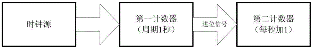
[0056] A clock device based on time stamp and counter, such as figure 1 As shown, it includes: a first counter and a second counter connected in sequence; the first counter can be used as a prescaler of the second counter, and each counting cycle can generate a carry signal to the second counter to drive the second counter to increase by 1, The process is completed in hardware without software intervention; the first counter can be automatically reloaded after the counting period ends, and the next counting period is automatically started.

[0057] Set the counting period of the first counter to 1S, that is, generate a carry signal to the second counter every second, and the second counter adds 1 every second. The value of the second counter can be used to represent the second value, and the value of the first counter can be used to calculate millisecond or higher precis...


PUM


Abstract

The invention discloses a clock device based on a timestamp and counters and an achieving method thereof.The clock device comprises the first counter and the second counter which are sequentially connected.The first counter serves as a prescaler of the second counter, and each counting period of the first counter can produce a carry signal for the second counter to drive the second counter to add one.After each counting period is finished, the first counter automatically reloads and begins the next counting period.The clock device has the advantages that the pure hardware clock can achieve very high clock precision (millisecond, microsecond and nanosecond), and the system time reading method can prevent reading errors caused by critical problems so that reading can be more reliable and high in timeliness; the timestamp is set to be in year 2,000, calculation can be simplified, and the time expression range can be enlarged; the RTC function can be achieved on a hardware platform without RTC.

Description

Technical field [0001] The invention relates to the technical field of system clocks, in particular to a clock device based on a time stamp and a counter and an implementation method thereof. Background technique [0002] Two times are mentioned in the present invention: [0003] (1)Calendar time: intuitive time format, expressing time as year, month, day, hour, minute, second, millisecond; [0004] (2) System time: based on the time representation of the time stamp, the time is expressed as the number of seconds + milliseconds elapsed since the time stamp, which is a form of time representation inside the embedded system; [0005] These two kinds of time are just different in representation form, and both can be used to represent the time at a certain moment, and the two forms of time can be interchanged. [0006] In embedded applications that require time stamping, hardware or software is required to provide a time mechanism, and the system needs to provide a real-time running clock ...

Claims


Application Information

Patent Timeline
Patent Type & Authority Applications(China)
IPC IPC(8): G06F1/14
CPCG06F1/14
Inventor 高彦斌孟祥军何军田李伟硕
Owner STATE GRID INTELLIGENCE TECH CO LTD
Why Eureka
Try Eureka