
Dual-band adjustable band-pass filter

A filter and band-tuning technology, which is applied to waveguide devices, resonators, electrical components, etc., can solve the problems of fewer dual-frequency adjustable band-pass filters, affecting high-pass bands, and large filter sizes.

Inactive Publication Date: 2016-06-29
SOUTH CHINA UNIV OF TECH
View PDF7 Cites 16 Cited by
  • Summary
  • Abstract
  • Description
  • Claims
  • Application Information

AI Technical Summary

Problems solved by technology

However, the center frequency of the low passband will affect the high passband during adjustment
[0006] In 2013, "Dual-bandbandpass filter with independently tunable center frequencies and bandwidth" published by G.Chaudhary et al. on IEEE Transaction on MTT used two sets of dual-mode resonators to realize a bandpass filter with adjustable center frequency and controllable bandwidth of the dual passband. However, due to the use of combined resonators, the size of the filter is larger
There are few published articles or patents related to dual-frequency tunable bandpass filters with controllable bandwidth

Method used


Image

  • Dual-band adjustable band-pass filter
  • Dual-band adjustable band-pass filter
  • Dual-band adjustable band-pass filter

Examples


Embodiment 1

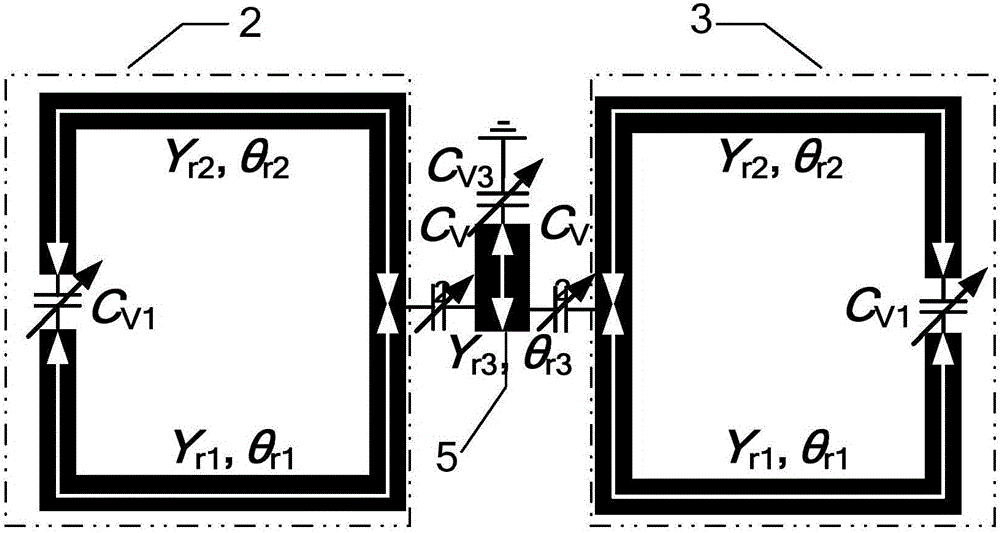
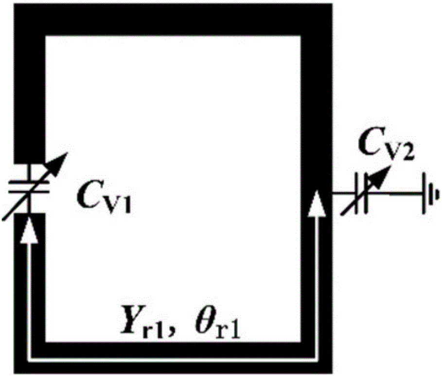
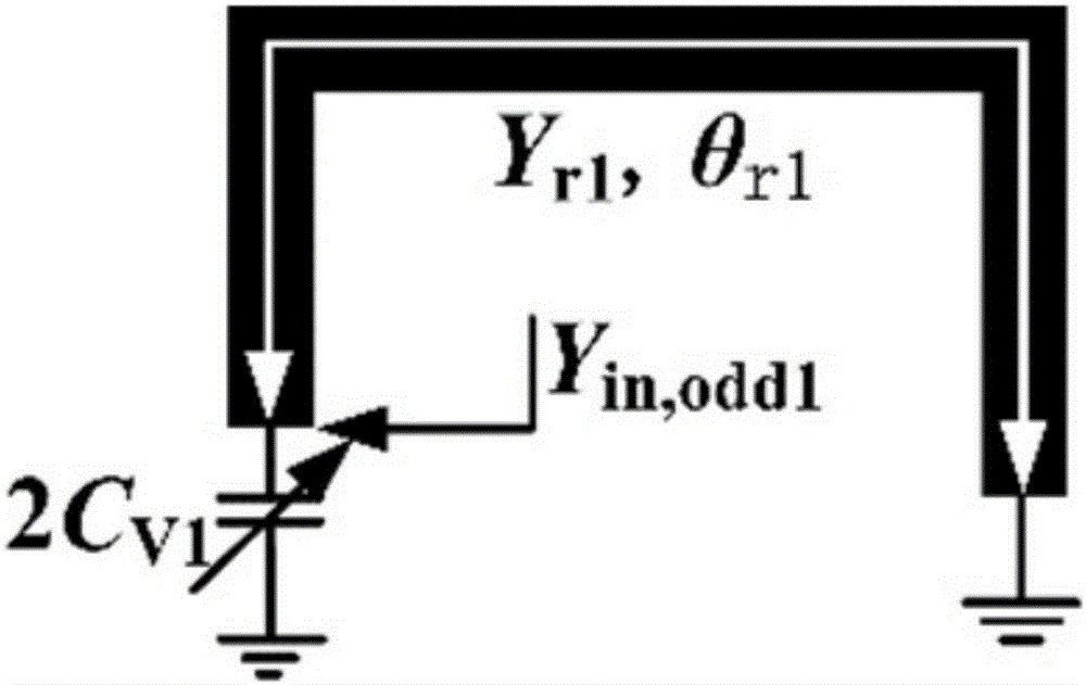
[0039] Such as figure 1 As shown, this embodiment proposes a three-mode resonator, the three-mode resonator includes two split ring resonators arranged in the opposite direction, and the two split ring resonators are respectively the first split ring resonator 2 and the second split ring resonator Split ring resonator 3, the openings of the first split ring resonator 2 and the second split ring resonator 3 are respectively covered by a varactor diode C V1 connected; followed by a set of series-connected varactor diodes C V2 The center of the first split ring resonator 2 and the second split ring resonator 3 is connected, and the varactor diode C in this group of series connection V2 A section of short open-circuit stub microstrip line 5 is loaded in the middle, and a varactor diode C is loaded at the end of the short open-circuit stub microstrip line 5V3 ;

[0040] The three-mode resonator as a whole presents a left-right symmetrical structure, therefore, the resonator can b...

Embodiment 2

[0043] According to the analysis of "L. Gao and X. Y. Zhang, "High-selectivity dual-bandband pass filter using a quad-moderesonator with sorce-loading coupling", IEEE Microw. Wireless Compon. Lett., vol.23, no.9, pp.474-476, Sep.2013." , by increasing the coupling between branches, one resonant mode can be split into two modes, and the two split modes are near the resonant mode, and the coupling coefficient between the two modes can be adjusted through the coupling part; In this embodiment, the two split-ring resonators in the three-mode resonator proposed in Embodiment 1 are partially coupled, as Figure 8 Shown, where θ r1 = θ stud1 +θ stud2 ; According to the previous analysis, compared with figure 1 The resonator in Figure 8 The resonator in not only has one more resonant mode, forming a four-mode resonator, but also can reduce the size of the resonator, which is beneficial to the miniaturization of the filter.

Embodiment 3

[0045] Such as Figure 9 As shown, the dual-frequency tunable bandpass filter of this embodiment is realized based on the four-mode resonator of Embodiment 2, including the microstrip line structure 1 of the upper layer, the dielectric substrate (not shown in the figure) of the middle layer, and the lower layer The ground metal plate (not shown in the figure) and the metal via hole (not shown in the figure), the microstrip line structure 1 and the ground metal plate are attached on the dielectric substrate, and the metal via hole runs through the microstrip line structure in turn 1. The dielectric substrate and the grounded metal plate are connected through the dielectric substrate between the microstrip line structure 1 and the grounded metal plate. The microstrip line structure 1 includes a multimode resonator and a pair of input / output feeders. The entire microstrip line Stripline structure 1 presents left-right symmetry;

[0046] The multimode resonator includes two split...


PUM


Abstract

The invention discloses a dual-band adjustable band-pass filter. The filter comprises an upper layer microstrip line structure, a middle layer dielectric substrate, a lower layer grounding metal plate and a metal through hole, wherein the microstrip line structure comprises a multi-mode resonator and a pair of input / output feeder lines; the multi-mode resonator comprises two split ring resonators that are arranged symmetrically left and right; the opening position of each split ring resonator is connected through a group of series-wound variable capacitance diodes; the centers of the two split ring resonators are connected through a group of series-wound variable capacitance diodes; a section of short open-circuit branch microstrip line, which is loaded by the variable capacitance diode at the tail end, is loaded in the middle of the group of the series-wound variable capacitance diodes; extra branch coupling is introduced to the space between the split ring resonators; and the input / output feeder lines are microstrip lines with one short-circuit ends and the other open-circuit ends. The two passbands of the filter are adjustable, and the bandwidth is controllable as well; and meanwhile, only one multi-mode resonator is adopted, so that the dual-band adjustable band-pass filter has relatively high advantage in miniaturization.

Description

technical field [0001] The invention relates to a band-pass filter, in particular to a dual-frequency adjustable band-pass filter applied to a dual-frequency reconfigurable radio frequency front-end system, and belongs to the technical field of microwave communication. Background technique [0002] During the rapid development of modern wireless communication systems, there is an increasing demand for systems that are compatible with multiple frequency bands to implement multiple services. As an important part of the RF front-end system, the RF electronically tunable filter has the advantages of small size, low cost, and flexibility, and is increasingly valued. Therefore, a band-pass filter that is compatible with multiple frequency bands, has controllable bandwidth, and can flexibly adjust the center frequency is more attractive, and has great significance for the research of dual-frequency adjustable band-pass filters. [0003] Single-band tunable filters have been widely...

Claims


Application Information

Patent Timeline
Patent Type & Authority Applications(China)
IPC IPC(8): H01P1/207H01P7/08
CPCH01P1/207H01P7/082
Inventor 褚庆昕张史轩
Owner SOUTH CHINA UNIV OF TECH
Learn More