Block type iron core winding method of compact permanent magnet brushless motor

A technology of permanent magnet brushless motor and winding method, which is applied in the direction of manufacturing motor generators, electrical components, electromechanical devices, etc., can solve the problems of small weight, difficult winding, and low tooth strength, and achieve simple structure and increased Work reliability, weight reduction effect

Active Publication Date: 2016-06-29
HARBIN INST OF TECH
View PDF7 Cites 3 Cited by
  • Summary
  • Abstract
  • Description
  • Claims
  • Application Information

AI Technical Summary

Problems solved by technology

[0006] The purpose of the present invention is to take into account the small weight, small volume and reliability of the motor, solve the problem that when the size of the motor is too small, the strength of the teeth is too small, and there will be difficulties in winding, and a compact permanent magnet brushless motor is provided. Segmented core winding method

Method used


Image

  • Block type iron core winding method of compact permanent magnet brushless motor
  • Block type iron core winding method of compact permanent magnet brushless motor
  • Block type iron core winding method of compact permanent magnet brushless motor

Examples


specific Embodiment approach 1

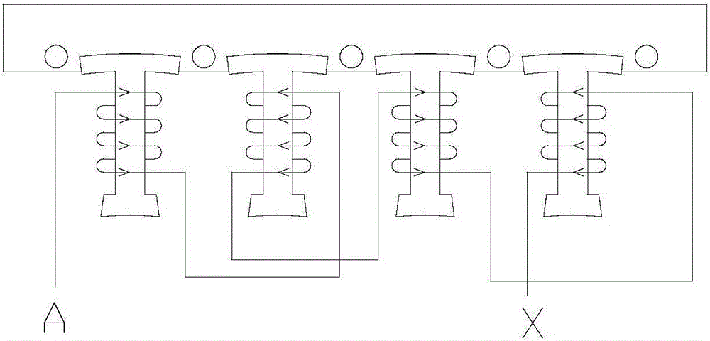
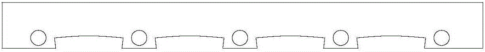
[0015] Specific implementation mode one: the following combination Figure 1 to Figure 3 This embodiment is described. In this embodiment, a segmented core winding method for a compact permanent magnet brushless motor is described. The compact permanent magnet brushless motor includes a hollow multi-pole permanent magnet rotor and a Hall element embedded Stator, the iron core of the stator is a segmented iron core structure, a plurality of stator teeth are set on the stator iron core, a stator slot is formed between every two stator teeth, and Hall elements are embedded in some stator slots;

[0016] Three-phase symmetrical windings are wound on the stator teeth, and the method of winding three-phase symmetrical windings is:

[0017] Fix the segmented stator core on the winding mold and fix it with a pressure plate; leave a gap the size of the winding head between the stator teeth for manual winding; after winding one stator tooth, continue to wind the next stator tooth , win...

specific Embodiment approach 2

[0022] Specific Embodiment 2: This embodiment will further explain Embodiment 1. Under the premise of ensuring that the overall three-phase stator winding is in a symmetrical state, the number of turns of the winding in the stator slot where the Hall element is placed is smaller than the number of turns without the Hall element. .

[0023] The overall three-phase stator winding is in a symmetrical state to ensure that the magnetic flux is distributed as evenly as possible to reduce the torque fluctuation of the permanent magnet motor.


PUM


Abstract

The invention discloses a block type iron core winding method of a compact permanent magnet brushless motor, and belongs to the field of the motor. According to the method provided by the invention, the low weight, small size and reliability of the motor are all taken into consideration, and the problem of winding difficulty resulting from too low tooth strength when the size of the motor is very small is solved. The compact permanent magnet brushless motor provided by the invention comprises a hollow multi-pole permanent magnet rotor and a stator in which Hall elements are embedded; the iron core of the stator is of segmented iron core structure; multiple stator teeth are arranged on the stator iron core; a stator slot is formed between every two stator teeth; three Hall elements are embedded in the stator slots in a three-phase symmetrical mode; three-phase symmetrical windings are winded on the stator teeth; the method for winding the three-phase symmetrical windings comprises following steps of fixing the stator iron core of the segmented structure on a winding die; fixing with pressure plates; reserving gaps among the stator teeth for manual winding, wherein the sizes of the gaps are the sizes of winding heads; after finishing winding one stator tooth; continuing to wind a next stator tooth, wherein all stator teeth under one phase are winded once.

Description

technical field [0001] The invention belongs to the technical field of motors. Background technique [0002] The space robotic arm is an important device necessary for space engineering, assisting astronauts to complete high-precision transportation and maintenance work. The design requirements of the mechanical arm are high strength, high reliability, flexible work and light volume and weight as possible. Electromagnetic devices are essential in the manipulator drive system. Compared with hydraulic drive and other common drive methods for ground manipulators, electromagnetic drive has great advantages in the space field. Therefore, as far as the current development of the space field is concerned, other countries with advanced space science and technology have adopted electromagnetic drive methods to solve the drive problem of space manipulators. [0003] As an important core equipment of electromagnetic drive, the motor has many technical difficulties in design and proc...

Claims


Application Information

Patent Timeline
IPC IPC(8): H02K15/085
CPCH02K15/085
Inventor 尚静刘雪缘刘承军胡建辉李昕珏江善林邹继斌徐永向李勇
Owner HARBIN INST OF TECH
Why Eureka
Try Eureka