Pressure foot unit of automatic drilling and riveting machine

An automatic drilling riveting machine and presser foot technology, applied in the field of machining, can solve the problems of riveting work influence, riveting parts cannot be pretreated, presser foot design can not control component reinforcement well, etc., to improve production efficiency and quality Effect

Inactive Publication Date: 2016-07-06
ZHEJIANG UNIV
View PDF6 Cites 9 Cited by
  • Summary
  • Abstract
  • Description
  • Claims
  • Application Information

AI Technical Summary

Problems solved by technology

The design of the presser foot in this technical solution cannot well control the reinforcement of components on different plates, and pretreatment cannot be performed on the riveted parts
Will have an impact on the next riveting work

Method used


Image

  • Pressure foot unit of automatic drilling and riveting machine
  • Pressure foot unit of automatic drilling and riveting machine
  • Pressure foot unit of automatic drilling and riveting machine

Examples


Embodiment Construction

[0042] The specific embodiments of the present invention will be described below in conjunction with the accompanying drawings.

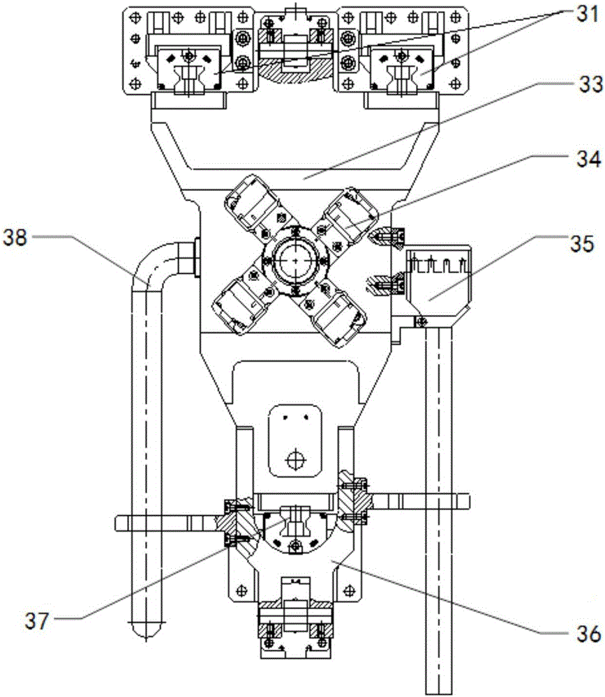
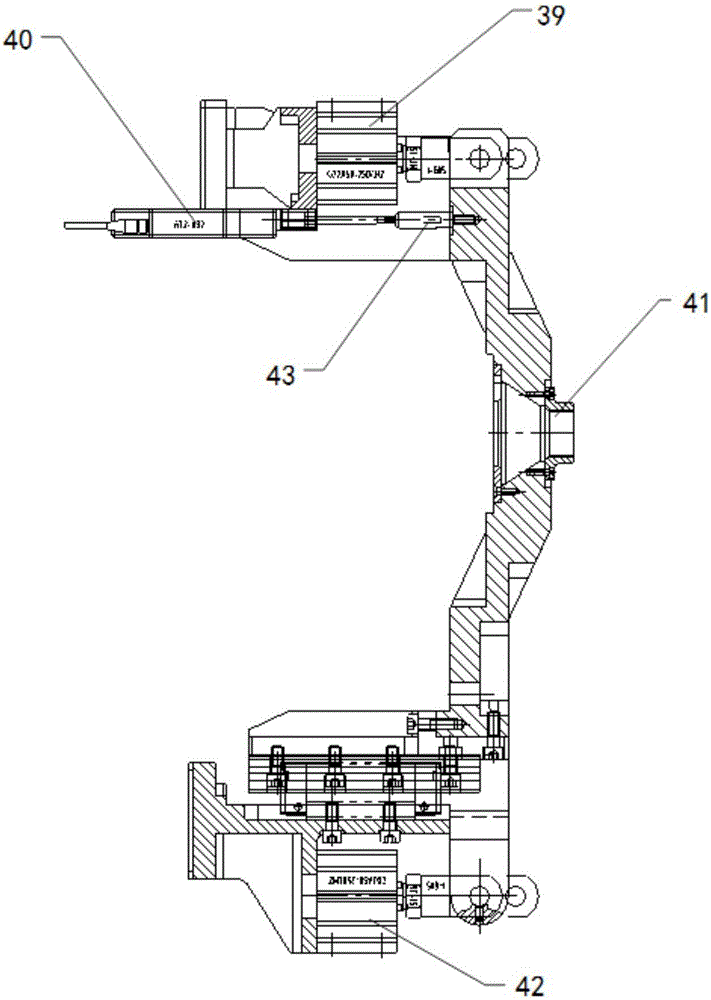
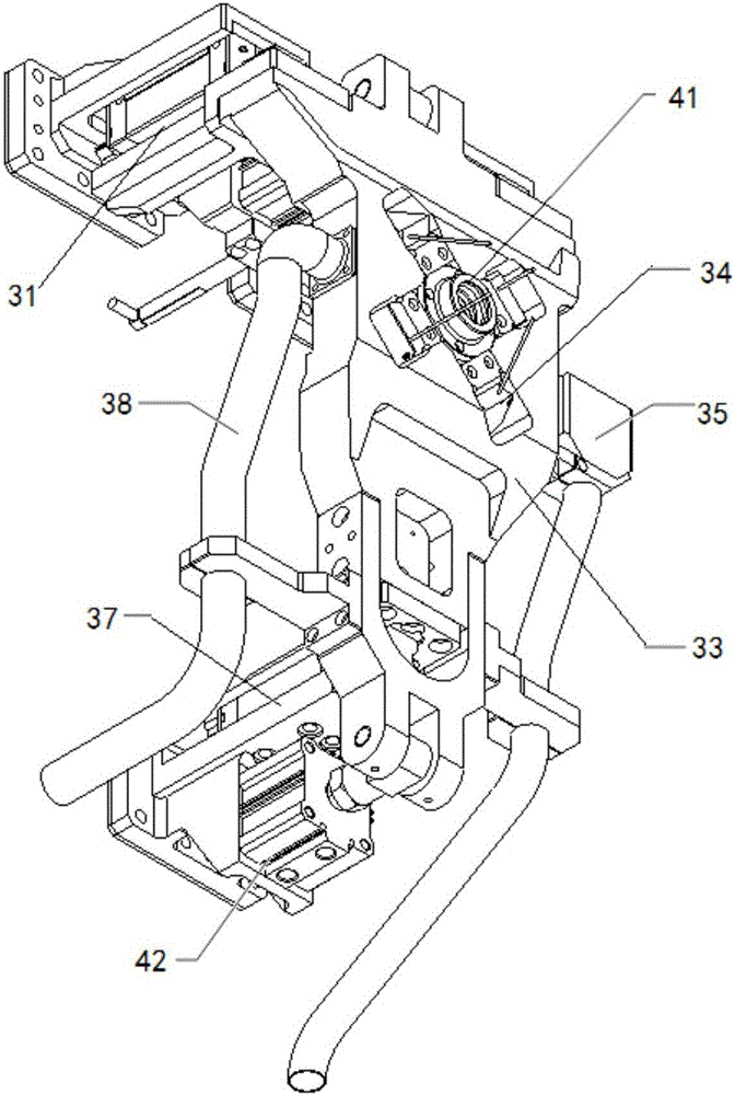
[0043] like Figure 1 ~ Figure 3 As shown, a presser foot unit of an automatic drilling and riveting machine passes through an upper guide rail 31, a presser foot body 33, a laser ranging sensor 34, a recovery assembly 35, a transition joint 36 under the presser foot, a lower guide rail 37, a chip removal pipe 38, an upper Driving cylinder 39, length gauge 40, presser foot head 41, lower driving cylinder 42 etc. are assembled. The entire presser foot unit is connected with the automatic drilling and riveting machine through the slider seat of the upper and lower guide rails. The presser foot main body 33 is connected with the upper guide rail 31 guide rail seat, and the upper driving cylinder 39 is installed on the upper guide rail slider base and is connected with the presser foot main body 33 by pins. The length gauge 40 is installed on the base...


PUM


Abstract

The invention discloses a presser foot unit of an automatic drilling and riveting machine. The presser foot unit comprises: a feed assembly connected with the automatic drilling and riveting machine and driving the presser foot unit; a presser foot main body installed on the feed assembly and completed Clamping action; laser distance measuring component, installed on the main body of the presser foot and providing the surface normal vector of the component processing position for the automatic drilling and riveting machine; chip removal component, installed on the main body of the presser foot and removing the debris formed by the hole Cleaning; recycling components, installed on the main body of the presser foot and recycling the unqualified rivets in the riveting process. The invention has the following advantages: through the laser distance measuring sensor, the method of riveting curved surface is determined, and the operation is controlled by feedback; the feed assembly is driven, and the riveting components are clamped tightly, eliminating the gap between the components and improving the rigidity of the components; multiple detections, realizing the hole making Precise control of depth and nail insertion depth; debris generated during hole making and riveting can be discharged through the chip discharge tube to avoid affecting subsequent operations.

Description

technical field [0001] The invention relates to the field of machining, in particular to a presser foot unit of an automatic drilling and riveting machine. Background technique [0002] Aircraft assembly is the main link of aircraft manufacturing, and riveting is the main connection method in the process of aircraft panel assembly. The quality and efficiency of riveting directly affect the quality and efficiency of aircraft assembly and aircraft manufacturing. In recent years, with the development of assembly technology, the use of automatic drilling and riveting machines has gradually replaced traditional manual riveting, and the riveting quality and riveting efficiency have been greatly improved. At present, the development and manufacture of domestic automatic drilling and riveting machines are still in a blank state, and the automatic drilling and riveting machines used by domestic aircraft manufacturers are all purchased from foreign manufacturers. [0003] The entire ...

Claims


Application Information

Patent Timeline
Patent Type & Authority Applications(China)
IPC IPC(8): B21J15/42B21J15/38B21J15/32B21J15/26
CPCB21J15/42B21J15/26B21J15/32B21J15/38
Inventor 柯映林蒋君侠柯臻铮董辉跃李江雄章明
Owner ZHEJIANG UNIV
Why Eureka
Try Eureka