Target back plate and magnetron sputtering device for magnetron sputtering

A magnetron sputtering and backplane technology, applied in the field of magnetron sputtering, can solve the problems of reduced utilization rate of target material 1, uneven film thickness of the substrate to be coated, low utilization rate of target material, etc. Effectiveness of utilization, extended service life, improved uniformity

Active Publication Date: 2018-01-26
BOE TECH GRP CO LTD +1
View PDF4 Cites 0 Cited by
  • Summary
  • Abstract
  • Description
  • Claims
  • Application Information

AI Technical Summary

Problems solved by technology

Therefore, when the target 1 is installed on the target back plate 2 that can form the above-mentioned magnetic field for magnetron sputtering, there is still a large margin in the middle of the target 1 when both ends of the target 1 are about to be broken down, causing the target The utilization rate of material 1 is reduced
[0003] In order to solve the above-mentioned problem of low utilization rate of the target material, although the utilization rate of the target material 1 is increased by thickening the two ends of the target material 1 in the prior art, due to the fast etching rate of the two ends of the target material 1, Correspondingly, the thickness of the film formed on both ends of the substrate to be coated is relatively thick, which will lead to uneven thickness of the film formed on the substrate to be coated.

Method used


Image

  • Target back plate and magnetron sputtering device for magnetron sputtering
  • Target back plate and magnetron sputtering device for magnetron sputtering
  • Target back plate and magnetron sputtering device for magnetron sputtering

Examples


Embodiment Construction

[0022] For ease of understanding, the target backing plate and the magnetron sputtering device provided by the embodiments of the present invention will be described in detail below with reference to the accompanying drawings.

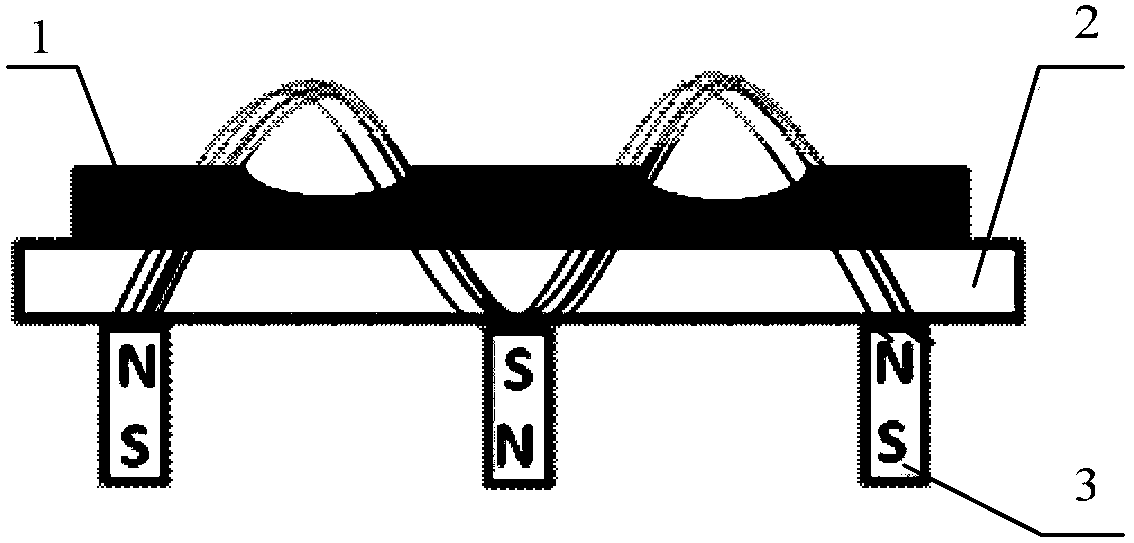
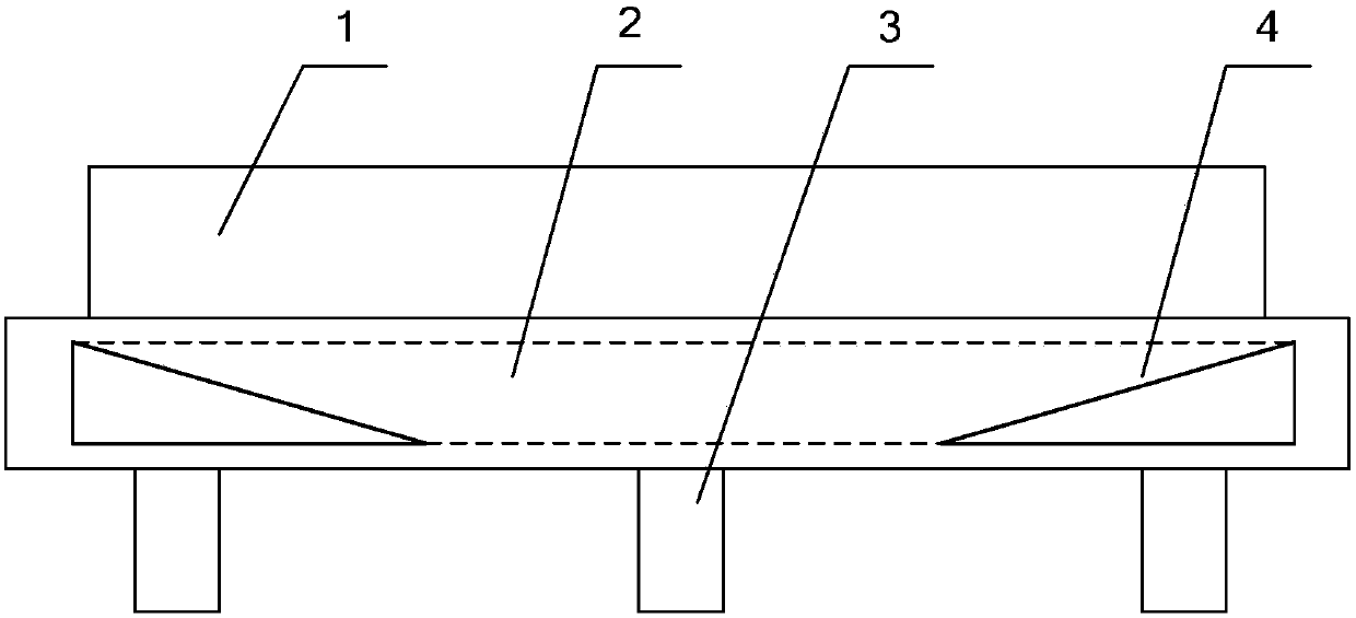
[0023] see figure 2 , in the embodiment provided by the present invention, the target back plate 2 is provided with a cooling liquid channel, the back of the target back plate 2 is provided with a plurality of magnets 3, and the cooling liquid channel of the target back plate 2 is also provided with a magnetic conductive sheet 4. The magnetically conductive sheet 4 corresponds to the strongest magnetic field strength area of ​​the magnetic field generated by the plurality of magnets 3 .

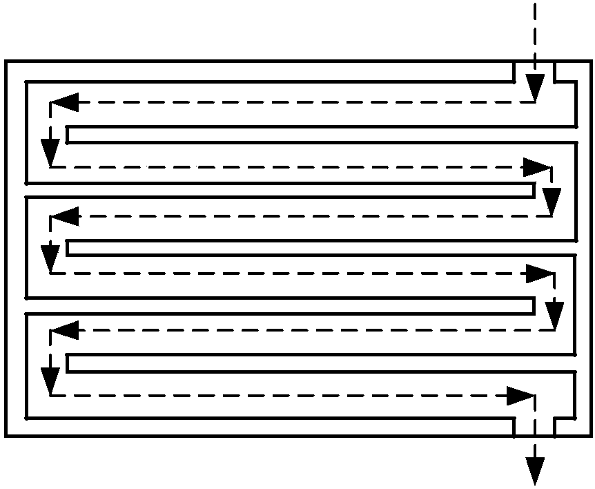
[0024] During specific implementation, the coolant channel provided in the target back plate 2 is as follows: image 3 As shown, the cooling liquid channel preferably adopts a serpentine channel, and there is a very thin separation plate at the adjacent channel of t...


PUM

PropertyMeasurementUnit
thicknessaaaaaaaaaa
thicknessaaaaaaaaaa

Abstract

The invention discloses a target back plate for magnetron sputtering and a magnetron sputtering device, relates to the technical field of magnetron sputtering, and aims to increase the utilization rate of a target material and improve the uniformity of the thickness of a film formed on a substrate to be coated. According to the target back plate for magnetron sputtering, a cooling fluid channel is formed inside the target back plate, a plurality of magnets are arranged on the back side of the target back plate, magnetic conductive pieces are arranged inside the cooling liquid channel in the target back plate; and the magnetic conductive pieces correspond to magnetic fields with the strongest magnetic intensity generated by the magnetic conductive pieces and the plurality of magnets. The target back plate for magnetron sputtering and the magnetron sputtering device, which are disclosed by the invention, are applied to planar film coating.

Description

technical field [0001] The invention relates to the technical field of magnetron sputtering, in particular to a target back plate and a magnetron sputtering device for magnetron sputtering. Background technique [0002] In existing magnetron sputtering devices, such as figure 1 As shown, the target 1 used is usually supported by a target back plate 2, especially a large planar target; a cooling liquid channel is provided inside the target back plate 2, and the target is cooled by the cooling liquid flowing through the cooling liquid channel. The target material 1 is cooled, so as not to affect the normal progress of the magnetron sputtering due to the high temperature of the target material 1. The magnetic field used in magnetron sputtering is provided by the magnet 3 installed on the back of the target back plate 2, and the magnetic field intensity distribution of the magnetic field is related to the arrangement of the magnet 3 installed on the back of the target back plat...

Claims


Application Information

Patent Timeline
Patent Type & Authority Patents(China)
IPC IPC(8): C23C14/35
CPCC23C14/3407C23C14/35
Inventor 邢宏伟穆慧慧吴斌李冬青石旭王小军吴祥一
Owner BOE TECH GRP CO LTD
Why Eureka
Try Eureka