Annular heat pipe array heat exchanger and heat exchange system comprising annular heat pipe array heat exchanger

An annular heat pipe and heat exchange system technology, applied in the field of heat exchange, can solve the problems such as the inability to exert the heat exchange capacity of the condensing side, the uneven temperature distribution of the condensing side, and the increase of the temperature difference between the evaporation end and the condensing end. The ability of uneven distribution of cold and heat sources is strong, the energy consumption of air conditioners is saved, and the flow resistance is reduced.

Active Publication Date: 2016-07-06
INST OF ENGINEERING THERMOPHYSICS - CHINESE ACAD OF SCI
View PDF6 Cites 6 Cited by
  • Summary
  • Abstract
  • Description
  • Claims
  • Application Information

AI Technical Summary

Problems solved by technology

However, due to the requirements of cleanliness, it is not possible to directly exchange indoor and outdoor air, but it is necessary to use efficient heat transfer equipment such as heat pipes
[0009] The heat pipe heat exchanger that separates the evaporating end and the condensing end adopts the method of connecting pipes. All the steam generated at the evaporating end is transported through the connecting pipes, resulting in increased flow resistance; the steam starts to condense at the entrance of the condensing side. There is less steam at the bottom, resulting in uneven temperature distribution of the condensing side, and the heat exchange capacity of the condensing side cannot be well utilized
On the other hand, if the area of ​​the machine room is large, the distance between the evaporation end and the condensation end is relatively long, resulting in an increase in the length of the connecting pipe, which will also result in an increase in thermal resistance.
If the thermal resistance of the heat pipe heat exchanger increases, it means that the temperature difference between the evaporating end and the condensing end increases, and the heat pipe heat exchanger can only be used in a lower outdoor temperature environment, resulting in a reduction in the number of available days throughout the year and a reduction in energy saving effect

Method used


Image

  • Annular heat pipe array heat exchanger and heat exchange system comprising annular heat pipe array heat exchanger
  • Annular heat pipe array heat exchanger and heat exchange system comprising annular heat pipe array heat exchanger
  • Annular heat pipe array heat exchanger and heat exchange system comprising annular heat pipe array heat exchanger

Examples


Embodiment Construction

[0045]In order to make the object, technical solution and advantages of the present invention clearer, the present invention will be further described in detail below in conjunction with specific embodiments and with reference to the accompanying drawings. In the specification, the same or similar reference numerals designate the same or similar components. The following description of the embodiments of the present invention with reference to the accompanying drawings is intended to explain the general inventive concept of the present invention, but should not be construed as a limitation of the present invention.

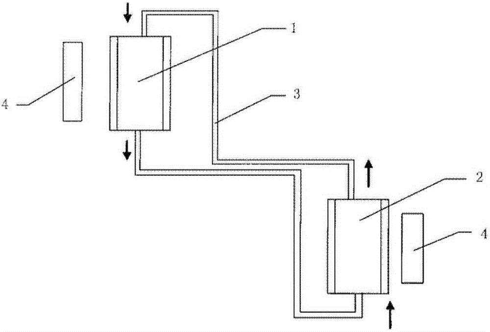
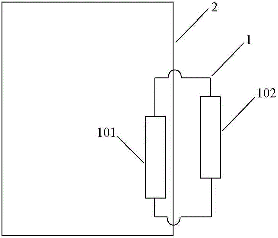
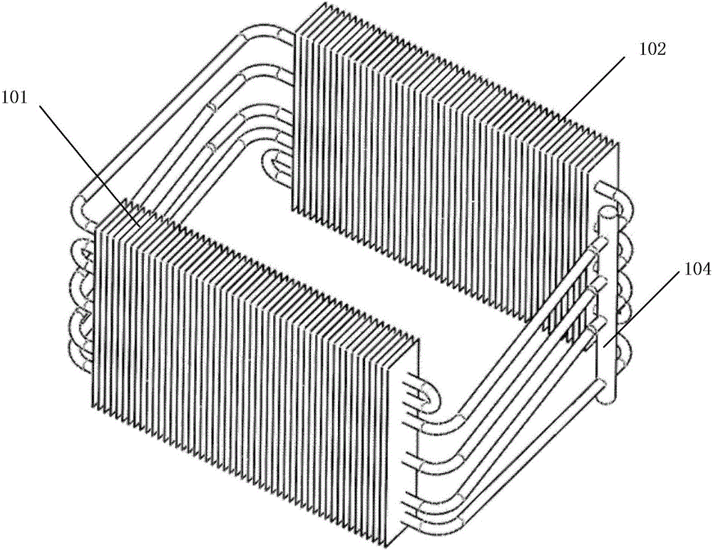
[0046] According to the general inventive concept of the present invention, an annular heat pipe array heat exchanger is provided, which includes a condensation end and an evaporation end, and realizes multi-loop heat exchange through two multi-pass pipelines arranged oppositely. The arrangement of each component will be described in detail below in conjunction wi...


PUM


Abstract

The invention relates to an annular heat pipe array heat exchanger. The annular heat pipe array heat exchanger comprises a condensation end and an evaporation end, and the condensation end and the evaporation end each comprises a plurality of horizontal pipes; the heat exchanger further comprises two multi-way pipes, and the two multi-way pipes are oppositely arranged; each multi-way pipe is connected to the horizontal pipes of the condensation end and the evaporation end to form a plurality of closed loops; and the two multi-way pipes include the first multi-way pipe and the second multi-way pipe. The invention further discloses a heat exchange system comprising the annular heat pipe array heat exchanger. According to the annular heat pipe array heat exchanger, the conditions that the outdoor temperature in Spring, Autumn and Winter is low and power consumption is less are used, heat inside the space is transferred to an outdoor place, a large amount of air-conditioning energy consumption is saved, and the annular heat pipe array heat exchanger can be applied to heat exchange in a data center or an equipment cabinet.

Description

technical field [0001] The invention relates to the field of heat exchange, and further relates to an annular heat pipe array heat exchanger and a heat exchange system comprising the heat exchanger. Background technique [0002] The energy consumption of data centers or communication cabinets is large and concentrated (the energy consumption per unit area is much higher than that of office buildings), 24 hours of uninterrupted operation, and the annual operating hours are much higher than other commercial buildings. With global warming and energy shortages, the problem of efficient energy utilization has become increasingly prominent. How to reduce power utilization efficiency (power utilization efficiency = total facility power / IT equipment power) has become the goal pursued by data center operation managers. [0003] According to the operation requirements of the equipment, the data center or the communication cabinet needs to ensure the reliable operation of the system in...

Claims


Application Information

Patent Timeline
Patent Type & Authority Applications(China)
IPC IPC(8): F24F13/30F28D15/02
CPCF24F13/30F28D15/0266
Inventor 王涛郭聪郭朝红曾秒姜玉雁
Owner INST OF ENGINEERING THERMOPHYSICS - CHINESE ACAD OF SCI
Why Eureka
Try Eureka