
Waste heat utilization cyclone separator

A cyclone separator and waste heat technology, applied in the direction of heat exchanger, indirect heat exchanger, cyclone device, etc., can solve the problem of increased resistance loss of flue gas in the dust collector, affecting the heat exchange effect of equipment, and increasing heat exchange Surface thermal resistance and other issues can be avoided to avoid waste heat loss, improve integration and reduce thermal resistance

Active Publication Date: 2017-07-25
ZHENGZHOU UNIV
View PDF8 Cites 0 Cited by
  • Summary
  • Abstract
  • Description
  • Claims
  • Application Information

AI Technical Summary

Problems solved by technology

Both methods have certain disadvantages: the first method is that the smoke and dust in the flue gas will block the flue gas channel of the heat exchanger, and after a long time, the high-temperature smoke and dust adhering to the heat exchange surface will increase the thermal resistance of the heat exchange surface , so the heat transfer efficiency is reduced, which affects the heat transfer effect of the equipment; and, for the waste heat recovery of high-temperature gas, it is easy to cause thermal stress corrosion
If the second method is used, the temperature of the flue gas will be reduced during the dust removal process in the dust removal equipment, resulting in a certain amount of waste heat loss
[0004] In addition, since the viscosity of high-temperature flue gas is higher than that of low-temperature flue gas, the resistance loss of flue gas in the dust collector increases, which requires more power consumption, resulting in waste of energy

Method used


Image

  • Waste heat utilization cyclone separator
  • Waste heat utilization cyclone separator
  • Waste heat utilization cyclone separator

Examples


Embodiment 1

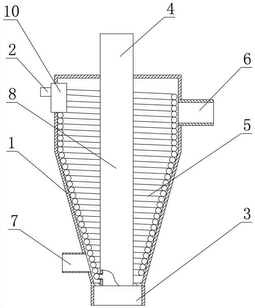
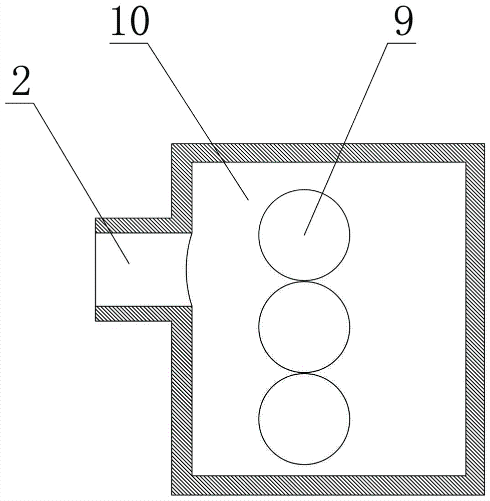
[0025] Such as figure 1 and figure 2 As shown, a waste heat utilization cyclone separator includes a housing 1, a dusty gas inlet 2 arranged on the side of the housing 1, an air inlet distributor 10, an ash discharge port 3 arranged at the lower end of the housing 1 and a device At the clean gas outlet 4 on the top of the housing 1, a group of spiral pipes 5 are arranged in the housing 1, and the upper ends of a group of the spiral pipes 5 are sealed and connected to the dust-containing gas inlet 2, and a group of the spiral pipes 5 The lower end of the ash discharge port 3 is sealed and communicated with the ash discharge port 3, and the ash discharge port 3 is sealed and connected with the clean gas outlet 4 through the air riser 8, and the ash discharge port 3 is isolated from the shell side space of the housing 1. A heat exchange medium inlet 6 and a heat exchange medium outlet 7 communicating with the shell side space are provided on the upper side and the lower side of...

Embodiment 2

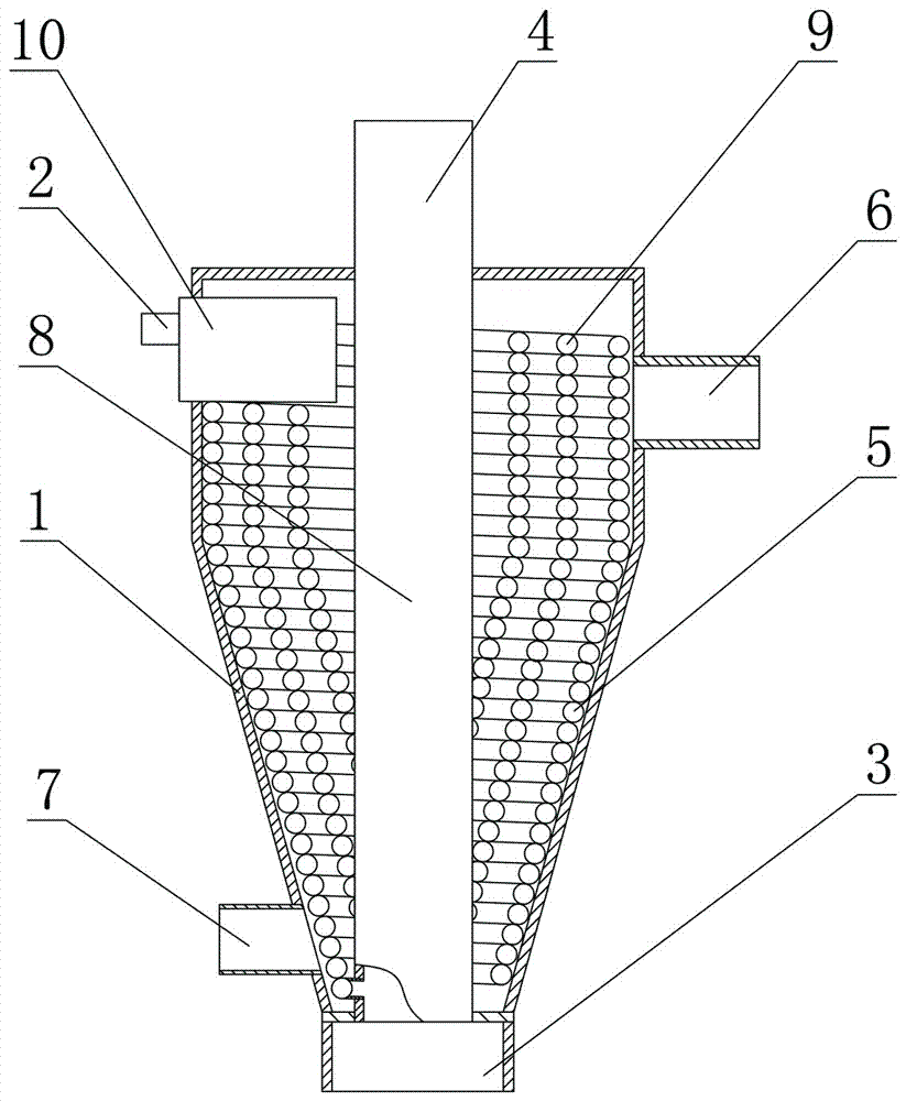
[0031] Such as image 3 As shown, the difference between this embodiment and Embodiment 1 is that it also includes at least one set of inner helical ducts 9, the upper end of each set of inner helical ducts 9 communicates with the dust-laden gas inlet 2, each set of inner helical ducts The lower end of the pipeline 9 communicates with the ash discharge port 3 , there is a gap between each group of internal spiral pipelines 9 , and there is a gap between the outermost group of internal spiral pipelines 9 and the spiral pipeline 5 . The lower end of the spiral duct 5 and the lower ends of the inner spiral ducts 9 are both pierced on the side wall below the air riser 8 , and then communicated with the ash discharge port 3 .

[0032] Add a sufficient number of spiral pipes to find a balance between ensuring the flow rate of high-temperature dust-laden gas and heat exchange efficiency, so as to achieve the best heat exchange capacity and solid-gas separation capacity.

[0033] In ...


PUM


Abstract

The invention provides an afterheat utilization cyclone separator, which comprises a casing, a dust-containing gas inlet, a gas inlet distributor, a dust discharging opening and a clean gas outlet, wherein the dust-containing gas inlet is formed in the lateral part of the casing; the dust discharging opening is formed in the lower end of the casing; the clean gas outlet is formed in the top of the casing; a group of spiral pipelines are arranged in the casing; the upper end of the group of the spiral pipelines is communicated with the dust-containing gas inlet in a sealed way; the lower end of the group of spiral pipelines is communicated with the dust discharging opening in a sealed way; the dust discharging opening is communicated with the clean gas outlet in a sealed way through a gas ascending pipe; the dust discharging opening is isolated from a shell space of the casing; the upper side and the lower side of the casing are respectively provided with a heat exchange medium inlet and a heat exchange medium outlet of the shell space. The dust-containing high-temperature gas enters the dust discharging opening through spiral pipes; gas in the spiral pipes flows at high speed, and performs heat exchange with heat exchange media of the shell space through the pipe wall; the heat exchange efficiency is improved; the heat exchange area is increased; the integral size is smaller; the integration degree is high.

Description

technical field [0001] The invention relates to a cyclone separator, in particular to a waste heat utilization cyclone separator. Background technique [0002] At present, China's industrial development has entered a new stage, and environmental problems such as air pollution and water pollution have become increasingly prominent, which have seriously affected people's normal life and health, and have attracted more and more attention. A large amount of organic gases harmful to the environment are produced in the industrial production process. In this case, it is necessary to increase the research and development of organic waste gas treatment technology, and reduce the harm to the atmospheric environment by improving waste gas treatment technology. In the chemical industry, solid-gas separation devices are often used to remove impurities such as dust particles in the gas. Cyclone separators are the most widely used, but a single cyclone separator cannot solve the problem o...

Claims


Application Information

Patent Timeline
Patent Type & Authority Patents(China)
IPC IPC(8): F28D7/02F28F19/01B04C9/00
CPCB04C9/00F28D7/024F28F19/01
Inventor 靳遵龙陈晓堂王永庆王长亮王元凯程海龙
Owner ZHENGZHOU UNIV
Learn More