
Linear steering engine loading device

A technology of loading device and steering gear, which is applied in the testing of measuring devices, machine/structural components, and the measurement of forces applied to control elements, etc. manufacturability, improved work efficiency, and low-cost effects

Active Publication Date: 2016-07-06
CHINA ACAD OF AEROSPACE AERODYNAMICS
View PDF5 Cites 6 Cited by
  • Summary
  • Abstract
  • Description
  • Claims
  • Application Information

AI Technical Summary

Problems solved by technology

[0002] When testing the output force of the aircraft steering gear, the commonly used hydraulic loading table, weight loading table and linear pneumatic loading table are used for loading; 1. The output force of the hydraulic loading table is large, but its structure is complex and prone to oil leakage
Moreover, due to the large output force of the hydraulic mechanism, it is not conducive to loading small output forces; 2. The weight loading platform is a simple mechanical loading device with weights, trays, etc. as the loading medium, and its structure is simple and the cost is low; but During the loading process, the load cannot be applied continuously, and due to the large inertia of the weight, it will impact the mechanical structures such as gears and keys inside the steering gear during repeated movements, resulting in permanent damage to the structure; 3. Linear pneumatic The loading table uses a permanent magnet DC motor as the actuator of the loading table to load the steering gear. The system converts the rotational motion of the torque motor into a linear motion through the movement of the swing rod; the working principle and device of this equipment are complicated and the cost is high

Method used


Image

  • Linear steering engine loading device
  • Linear steering engine loading device
  • Linear steering engine loading device

Examples


Embodiment Construction

[0032] Below in conjunction with accompanying drawing and specific embodiment the present invention is described in further detail:

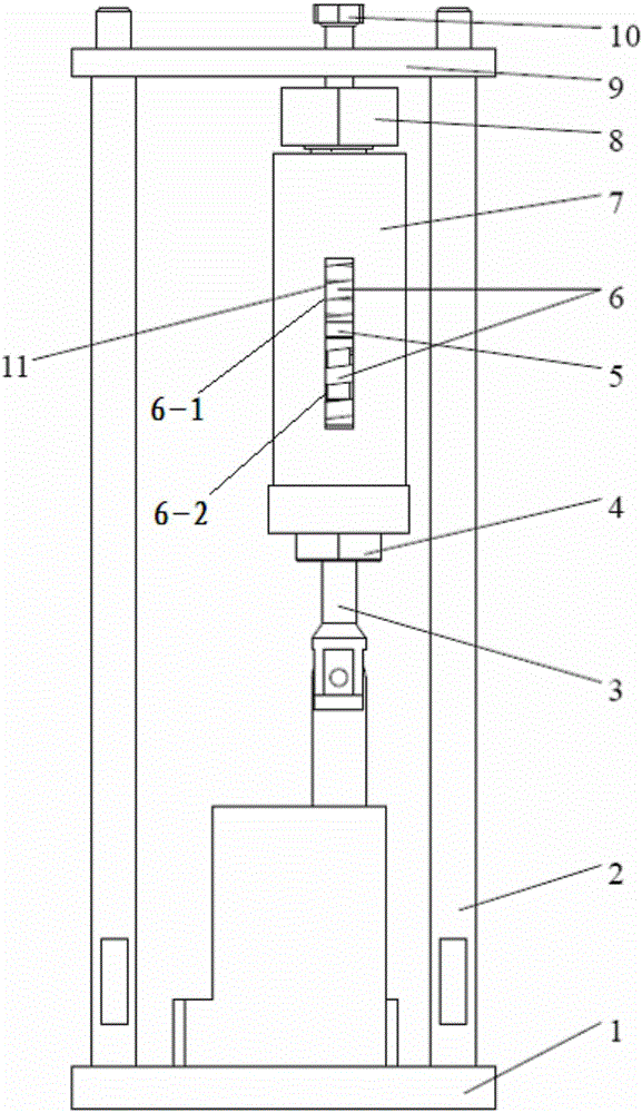
[0033] like figure 1 Shown is the structural diagram of the linear steering gear loading device. It can be seen from the figure that it includes the lower base plate 1, the column 2, the connecting rod 3, the end cover 4, the piston 5, the spring 6, the casing 7, the nut 8, the upper base plate 9, and the bolt 10 and the display window 11; the thread and the nut passed by the upper base plate 9 are installed on the column 2; the upper base plate 9 is installed on the lower base plate 1 through the column 2; One end is fixedly connected; the other end of the connecting rod 3 extends into the shell 7 through the end cover 4, and the connecting rod 3 and the piston 5 are connected by pins; the end cover 4 is tightened on the lower part of the shell 7; the shell 7 is installed on the upper bottom plate 9 through bolts 10 The lower part is locked wi...


PUM

PropertyMeasurementUnit
Outer diameteraaaaaaaaaa

Abstract

The present invention discloses a linear steering engine loading device, and relates to the loading device field used for testing the aircraft steering engine output force. The linear steering engine loading device comprises a lower bottom plate, a connecting rod, a spring set, a shell and an upper bottom plate, a steering engine is fixed on the lower bottom plate, and an output shaft of the steering engine is connected with one end of the connecting rod. The other end of the connecting rod is connected with a piston, and the piston is connected with the spring set with the help of an end cover and via the shell. The shell is installed on the upper bottom plate via nuts and bolts, and the upper bottom plate is installed on the lower bottom plate via the upright columns. The beneficial effects of the present invention are that: the actual tension and pressure born by the output shaft of the steering engine can be seen basically clearly while the linear loading is carried out on the steering engine; the inertia of the whole set of mechanisms is smaller, when the output shaft of the steering engine moves rapidly, a gear assembly inside the steering engine is not damaged due to the inertia of the whole set of mechanisms, and two steering engines of symmetrical structure can be loaded simultaneously, the structure is simple, and the realization cost is lower.

Description

technical field [0001] The invention relates to the field of a loading device for testing the output force of an aircraft steering gear, in particular to a loading device for a linear steering gear. Background technique [0002] When testing the output force of the aircraft steering gear, the commonly used hydraulic loading table, weight loading table and linear pneumatic loading table are used for loading; 1. The output force of the hydraulic loading table is large, but its structure is complex and prone to oil leakage. Moreover, due to the large output force of the hydraulic mechanism, it is not conducive to loading small output forces; 2. The weight loading platform is a simple mechanical loading device with weights, trays, etc. as the loading medium, and its structure is simple and the cost is low; but During the loading process, the load cannot be applied continuously, and due to the large inertia of the weight, it will impact the mechanical structures such as gears and...

Claims


Application Information

Patent Timeline
IPC IPC(8): G01L5/22G01M99/00
CPCG01L5/22G01M99/007
Inventor 王丽雅姜涛于德洋王刚李玲朱觉锦李晗张志新
Owner CHINA ACAD OF AEROSPACE AERODYNAMICS
Learn More