Driving path planning method and device and automatic steering system

A driving path and driving route technology, applied in control/adjustment systems, vehicle position/route/height control, motor vehicles and other directions, can solve problems such as driving obstacles, restrictions, etc., to simplify operations, reduce forced merging, and reduce errors effect of operation

Active Publication Date: 2016-07-06
DALIAN ROILAND SCI & TECH CO LTD
View PDF5 Cites 23 Cited by
  • Summary
  • Abstract
  • Description
  • Claims
  • Application Information

AI Technical Summary

Problems solved by technology

[0003] In order to solve the problem that driving is hindered or restricted by vehicles on the current road section during driving on the existing planned route, the present invention proposes a driving route planning method to find the optimal route on the planned route, so as to realize automatic driving route planning in process

Method used


Image

  • Driving path planning method and device and automatic steering system
  • Driving path planning method and device and automatic steering system
  • Driving path planning method and device and automatic steering system

Examples


Embodiment 1

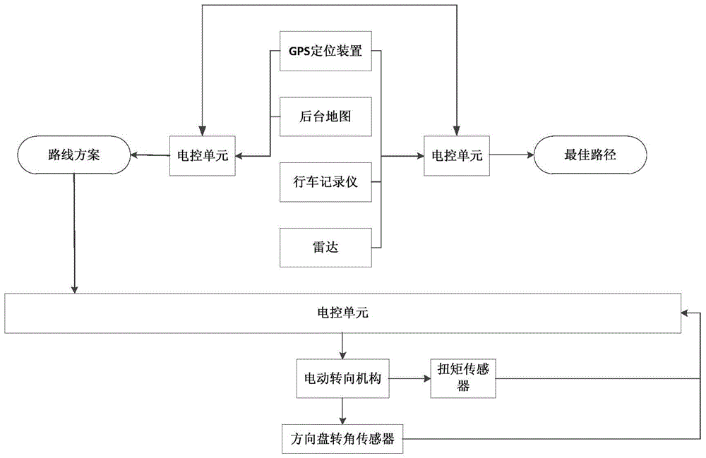
[0018] Example 1: A driving route planning method, in which a plurality of driving routes from the starting point to the ending point are planned by the background map, and one of the routes is selected for driving; during the driving process, the GPS positioning device verifies that the current driving route is the planned route; the GSP positioning device can locate in real time, The GPS positioning device plays a guiding role. First, there is a planned route, and then the GPS position represents the vehicle as a dynamic tracking point to describe the trajectory. That is to say, the GPS positioning position is always on the planned route of the background map and will not deviate; even if there is a wrong intersection, the system will re-plan a new route, and the GPS position will be used as the starting point of the new route In addition, GPS only has a positioning function, and what it represents is the precise position of the vehicle on the planned route. The radar of t...

Embodiment 2

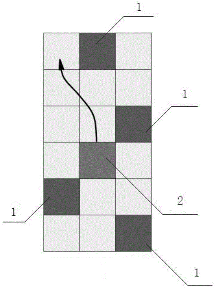
[0020] Example 2: It has the same technical solution as that of Embodiment 1, and more specifically: after planning the path of the drawing point, the vehicle continues to drive. Since the installation position of the driving recorder is fixed, the scene captured by the driving recorder represents the direction of the vehicle head, that is, the direction of the vehicle. . The driving recorder confirms the direction of travel, the driving lane, and the location of the target lane, and feeds back the image information to the host to correct the lane information on the grid map and confirm whether the coordinate points of the best path drawn are correct. First, there will be information on the number of lane lines in the background map information, that is, there are two (one-way) four (eight) lanes on the current driving road, and there will be corresponding lane lines; second, there will be the same number of lane lines in the vehicle grid map The lane line information is bui...

Embodiment 3

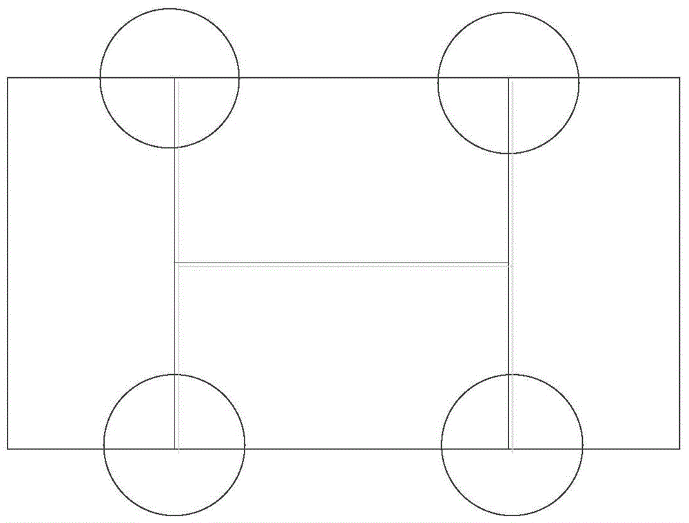
[0023] Embodiment 3: A driving path planning device, including a background map, a GPS positioning device, a radar, and a host; the background map plans a plurality of driving routes from the starting point to the ending point, and selects one of the driving routes; during driving, the GPS positioning device verifies the current driving route In order to plan the route; the radar of the vehicle detects the obstacles around the vehicle, and the detection data is input into the electronic control, and the electronic control inputs the coordinate information into the grid map, and plans the best route in the form of the grid map. There are a number of radars installed around the vehicle. The obstacles around the vehicle are detected by the radar. The detection data is input into the grid map with coordinate information. The grid map takes the midpoint of the line connecting the midpoints of the two axes as the origin. The axis is the line connecting the centers of the two opposi...


PUM


Abstract

The invention provides a driving path planning method and device and an automatic steering system, belongs to the field of automobile automatic driving, and aims at solving the problems in existing planning path driving that driving is obstructed or limited by vehicles on the current road segment. The technical key points are that multiple driving paths from the start point to the destination are planned by a background map, and one of the paths is selected for driving. The method is characterized in that a GPS positioning device verifies that the current driving path is a planning path in the driving process; and radar of the vehicle detects obstacles around the vehicle, the detection data are inputted to a grid map in the form of coordinate information, and the optimal path is planned in the form of the grid map. The effects are that path planning in the automatic driving process is realized through seeking of searching of the optimal path on the planning path.

Description

technical field [0001] The invention belongs to the field of automobile automatic driving, and relates to a driving path planning method and device. Background technique [0002] As a means of transportation in the 21st century, automobiles play an important role in human work and life, and have become an indispensable part of millions of families. There are more and more vehicles on the road, more and more crowded, and the road conditions are becoming more and more complex. While providing convenience for our life, the requirements for drivers are getting higher and higher, and the long-term low-speed congested road conditions are easy to make driving difficult. In order to reduce the driver's fatigue, in order to reduce the difficulty of the driver's operation, improve driving safety, reduce traffic accidents, and make our travel routes more scientific, intelligent and reasonable. At present, the existing technology can design and plan the travel route according to the cu...

Claims


Application Information

Patent Timeline
Patent Type & Authority Applications(China)
IPC IPC(8): G05D1/02
CPCG05D1/0278G05D2201/0213
Inventor 田雨农刘杨王强
Owner DALIAN ROILAND SCI & TECH CO LTD
Why Eureka
Try Eureka