Horizontal visual angle estimation and calibration method based on depth camera

A technology of depth camera and horizontal viewing angle, applied in the field of eye tracking, which can solve the problems of inability to promote, inflexible operation, and large head restrictions.

Inactive Publication Date: 2016-07-06
HOHAI UNIV CHANGZHOU
View PDF1 Cites 21 Cited by
  • Summary
  • Abstract
  • Description
  • Claims
  • Application Information

AI Technical Summary

Problems solved by technology

[0004] The purpose of the present invention is to overcome the deficiencies in the prior art and provide a method for estimating and calibrating the horizontal angle of view based on the depth camera, which so

Method used


Image

  • Horizontal visual angle estimation and calibration method based on depth camera
  • Horizontal visual angle estimation and calibration method based on depth camera
  • Horizontal visual angle estimation and calibration method based on depth camera

Examples


Embodiment Construction

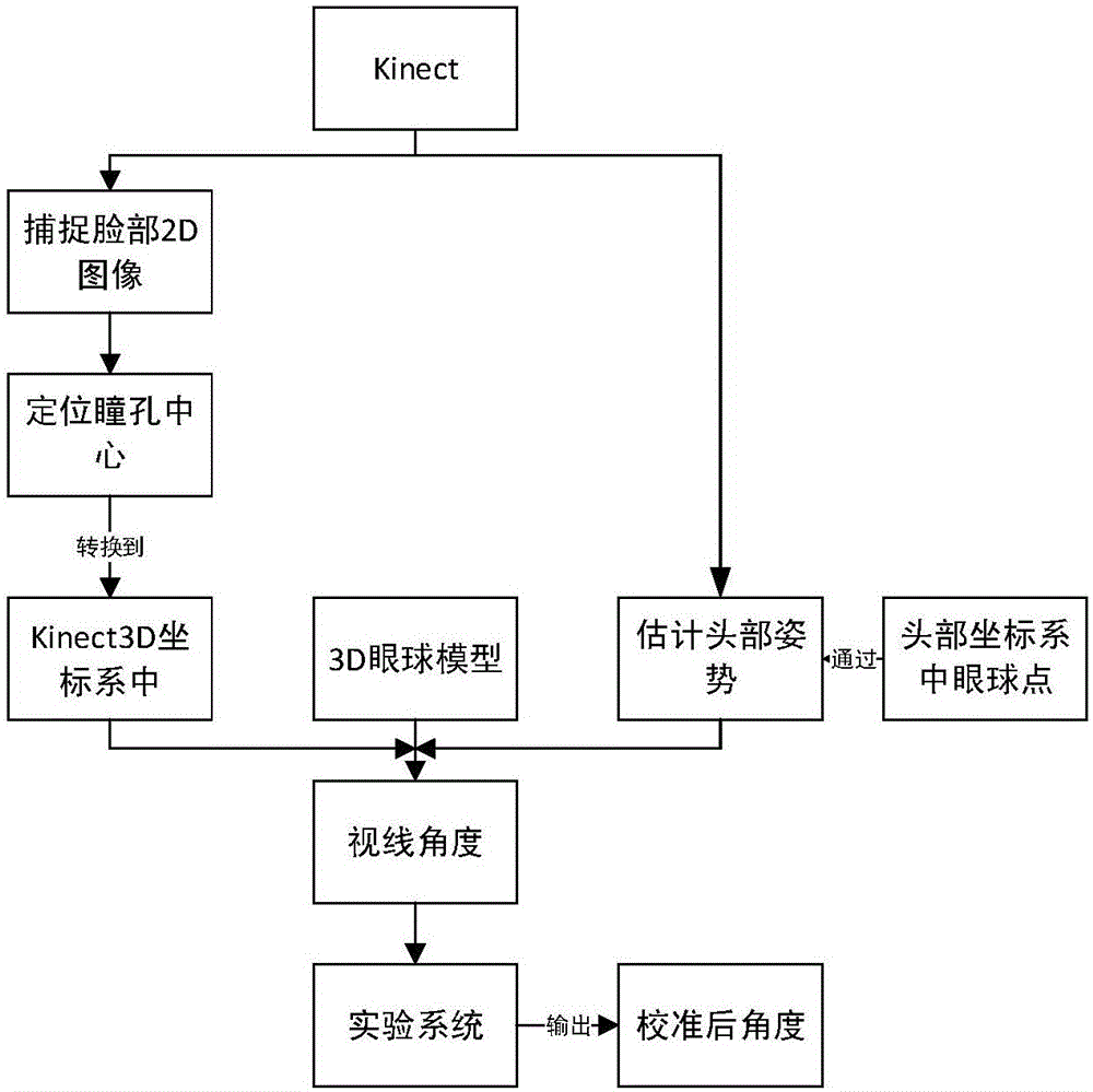
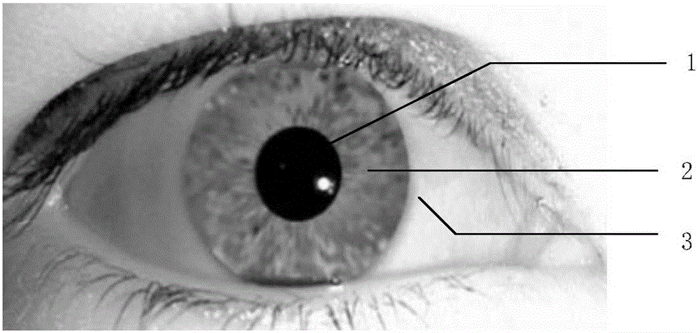
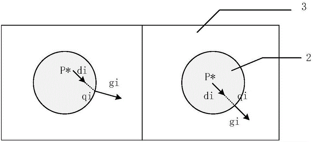
[0049] The present invention is based on the horizontal viewing angle estimation and calibration method of the depth camera 5. The method adopts the Kinect depth camera 5 to obtain the 3-dimensional coordinates of facial feature points, and uses a pupil 1 positioning algorithm, a 3D eyeball model and a preset eyeball center point. , to get the horizontal line-of-sight angle. The resulting line-of-sight angles are then calibrated through an experimental system.

[0050] The present invention will be further described below in conjunction with the accompanying drawings. The following examples are only used to illustrate the technical solution of the present invention more clearly, but not to limit the protection scope of the present invention.

[0051] Such as figure 1 Shown, is the flowchart of the inventive method, comprises the steps:

[0052] Step 1: Use the Kinect depth camera 5 to capture a 2D image of the face and estimate the head pose.

[0053] The present invention...


PUM


Abstract

The invention discloses a horizontal visual angle estimation and calibration method based on a depth camera, comprising steps of adopting a Kinect depth camera to capture a human face 2D image and an estimation head posture, ;positioning an optimal pupil center point in a the2D image to obtain the 2D coordinate of the optimal pupil center point, ;using a fixed an intrinsic parameter of a Kinect depth camera to convert the 2D coordinator of the optimal pupil center point obtained from the step 2 to a 3D coordinate system of the Kinect depth camera to obtain the 3D coordinator of the optimal pupil center point, ;using the 3D eyeball model to estimate the horizontal sight line angle, ;and designing a test system and obtaining the sight line angle through calibration. The method is simple in operation, good in instantaneity, and low in cost and has low limitation on the head of the tester and has the high accuracy.

Description

technical field [0001] The invention relates to a method for estimating and calibrating a horizontal viewing angle based on a depth camera, and belongs to the technical field of sight tracking. Background technique [0002] Eye-sight detection technology is a hot research topic at home and abroad at present, and it has a wide range of applications in human-computer interaction, communication of the disabled, safety monitoring and fatigue driving. Generally, its detection methods are divided into two categories: appearance-based methods and model-based methods. The former establishes a mapping relationship from high-dimensional features to low-dimensional target space, and the latter generally builds 3D models based on the features of the head and eyes. [0003] At present, eye trackers based on line of sight detection on the market still have obvious defects: first, the detection equipment is complicated and the cost is high; second, there are large restrictions on the head...

Claims


Application Information

Patent Timeline
IPC IPC(8): G06K9/00
CPCG06T3/40G06T15/005G06T2207/30041G06T2207/10004G06V40/166G06V40/19
Inventor 刘小峰倪剑帆周小芹蒋爱民徐宁
Owner HOHAI UNIV CHANGZHOU
Why Eureka
Try Eureka