
Multi-beam forward-looking sonar target detection method

A forward-looking sonar and target detection technology, applied in image data processing, instrumentation, computing, etc., can solve the problems of large detection step angle, low resolution, and difficulty in determining the true position of the target, so as to reduce processing pressure and complexity. The effect of improving the quality of sonar images and improving the detection accuracy

Inactive Publication Date: 2016-07-06
710TH RES INST OF CHINA SHIPBUILDING IND CORP
View PDF4 Cites 7 Cited by
  • Summary
  • Abstract
  • Description
  • Claims
  • Application Information

AI Technical Summary

Problems solved by technology

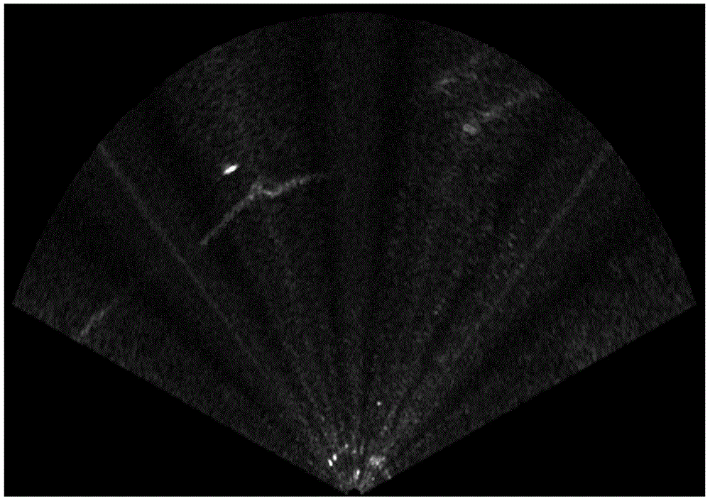
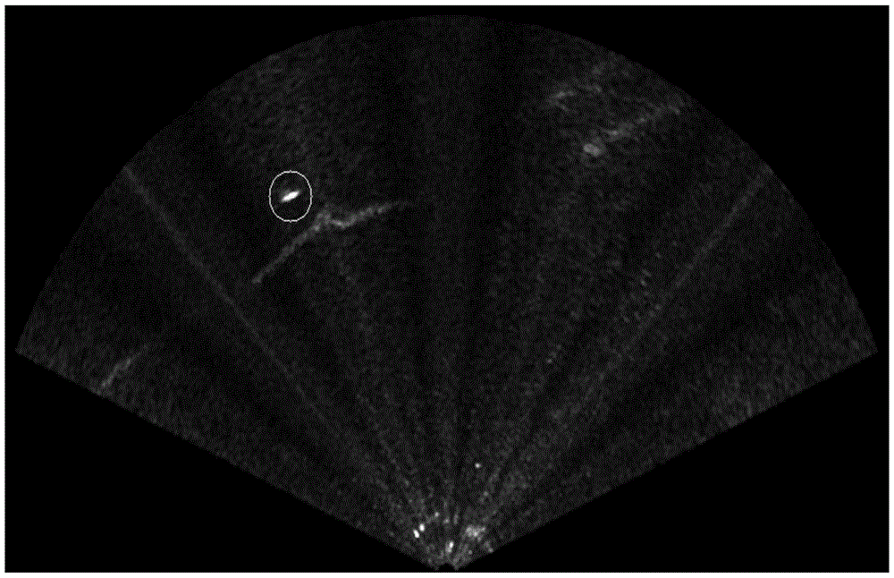
[0003] Although the multi-beam forward-looking sonar image is the same as the optical image, it is essentially a planar or spatial distribution map of energy, but because of the complex and changeable characteristics of the underwater acoustic channel, as well as the projection and scattering characteristics of the sound wave itself, making Its image is very different from the optical image
The multi-beam forward-looking sonar image in the underwater environment mainly has the following characteristics: (1) Low resolution: the wavelength of the detection sound wave emitted by the sonar detection device is generally longer, and the detection step angle is larger, and the distance between adjacent beams is not Continuously changing, with a certain interval, resulting in low resolution of the sonar image
(2) Serious noise interference: the underwater acoustic channel and the ocean environment are complex and changeable, and there are interferences of attenuation, reverberation, and scattering during the propagation of sound waves
In addition, other sounds in the marine environment are also the main source of sonar image noise, and targets are often submerged in these disturbances, making it difficult to detect
(3) Multipath phenomenon: Multipath phenomenon is caused by the propagation of sound waves in the process of propagation, so that a target has multiple return values, resulting in ghosting in the image, making it difficult to determine the true position of the target

Method used


Image

  • Multi-beam forward-looking sonar target detection method
  • Multi-beam forward-looking sonar target detection method
  • Multi-beam forward-looking sonar target detection method

Examples


Embodiment Construction

[0029] The present invention will be described in detail below with reference to the accompanying drawings and examples.

[0030] The invention provides a multi-beam forward-looking sonar target detection method, which specifically includes the following steps:

[0031] Step 1: Perform low-pass filtering on the original multi-beam forward-looking sonar image X1 to obtain a low-noise sonar image X2.

[0032] The original image noise of multi-beam forward-looking sonar is relatively large, and the image noise is mainly caused by the scattering of particles in the water and the diffuse reflection of water surface waves. These noises appear as white reflection areas with different areas and irregular distribution on the multi-beam forward-looking sonar image, with strong intensity, and have the characteristics of time-varying and space-varying jumps, and their position and intensity in the image are random probability distributed. Commonly used low-pass filtering methods are not...


PUM


Abstract

The invention discloses a multi-beam forward-looking sonar target detection method. A target can be effectively detected by using the multi-beam forward-looking sonar target detection method. The multi-beam forward-looking sonar target detection method comprises the steps of: firstly, removing scattering noise in an image by using a median filter based on a 3*3 window to improve the quality of a sonar image; then, carrying out fixed threshold segmentation, segmenting a target and a background, performing an erosion operation by using a 3*3 rectangular window kernel, wherein the erosion operation of a morphological operation is capable of well removing a false target with a small area, that is the noise is further reduced, the processing pressure and complexity of identifying processing are alleviated; finally, further removing the false target by using an area ratio and a major-minor axis data ratio, therefore the correct rate of detection is improved.

Description

technical field [0001] The invention relates to the technical field of digital image processing, in particular to a multi-beam forward-looking sonar target detection method. Background technique [0002] With the development of science and technology and the in-depth study of autonomous underwater robots, sonar technology has been developed by leaps and bounds. The attention and research on imaging sonar is also rapidly maturing. There are already acoustic holographic imaging test systems close to optical image quality, sonic mirror imaging systems, etc. Although the quality of acoustic images obtained by these imaging systems is good, they are not suitable for real environments. . The underwater open environment in practical applications has high requirements for sensors, and it is necessary to accurately perceive the real information of the surrounding environment. Active sonar is the most widely used detection equipment for autonomous underwater vehicles, and multi-beam...

Claims


Application Information

Patent Timeline
IPC IPC(8): G06T7/00
CPCG06T2207/20032
Inventor 林飞宇石涛陈尧杨海鹏刘春宇
Owner 710TH RES INST OF CHINA SHIPBUILDING IND CORP
Learn More