Composite plate for heat dissipation and thermal runaway propagation prevention of battery system

A battery system and composite board technology, applied in the direction of secondary batteries, circuits, electrical components, etc., can solve the problems of reducing the performance of thermal runaway propagation, difficulty in synergy, and uneven temperature distribution of batteries, achieving good market prospects, Improved uniformity and simple structure

Active Publication Date: 2016-07-06
安徽中科久安新能源有限公司
View PDF8 Cites 48 Cited by
  • Summary
  • Abstract
  • Description
  • Claims
  • Application Information

AI Technical Summary

Problems solved by technology

[0005] At present, there is a contradiction between system heat dissipation and thermal runaway barrier in electric vehicles, and it is difficult for the two to have a good synergy
On the one hand, increasing the isolation measures will make it difficult for the system to dissipate heat,

Method used


Image

  • Composite plate for heat dissipation and thermal runaway propagation prevention of battery system
  • Composite plate for heat dissipation and thermal runaway propagation prevention of battery system
  • Composite plate for heat dissipation and thermal runaway propagation prevention of battery system

Examples


Embodiment 1

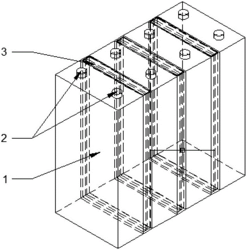
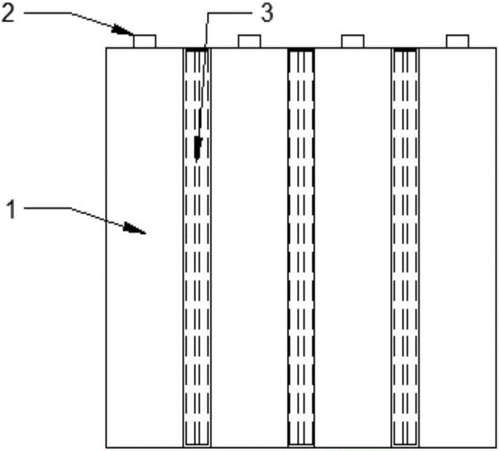
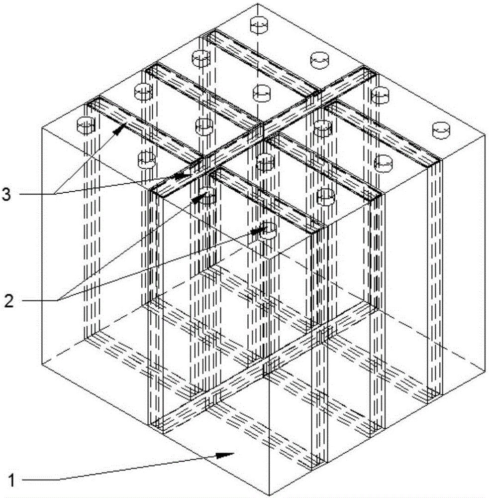
[0043] On the one hand, in order to study the heat dissipation capability of the composite board 3, 4 different structures were designed for comparative analysis, namely: the close contact between the battery cells 1, the air gap of 1 cm between the battery cells 1, and the battery cells. Install a 1 cm thermal conductive plate between 1 and a 1 cm composite plate 3 between the battery cells 1 . Place 3 battery cells 1 in the battery box, let each battery cell 1 discharge at the same rate, and then change the discharge rate (1C, 3C, 5C, 10C), and compare the maximum temperature and maximum temperature difference.

[0044] from Figure 8 It can be seen that there is little difference in the maximum temperature between the air space between the battery cells and the tight fit, indicating that simply increasing the space between the cells cannot effectively improve the heat dissipation capacity of the battery pack. The installation of thermal conductive plates between the batte...

Embodiment 2

[0046] On the other hand, in order to study the thermal runaway barrier capability of the composite board 3, and to simulate the thermal runaway situation of the battery, the first battery cell 1 is used as a thermal runaway battery, and the heat release rate is equivalent to the discharge heat generation at 10C, and the duration For 2000s, the remaining two battery cells 1 do not work. Here, the criterion for the start of thermal runaway of the battery is that the temperature of the battery cell 1 reaches 373.15K. Based on this, the time interval Δt of the thermal runaway of two adjacent batteries is calculated to analyze the respective thermal runaway barrier capabilities.

[0047] It can be seen from Table 1 that although the time interval Δt for the thermal runaway of the two batteries is the longest under the condition that the battery cells are separated by air, the temperature of the first thermal runaway battery can reach 354°C after 2000s, which is much higher than Co...


PUM

PropertyMeasurementUnit
Thermal conductivityaaaaaaaaaa

Abstract

The invention discloses a composite plate for heat dissipation and thermal runaway propagation prevention of a battery system. The composite plate comprises a heat conduction shell, a phase changing material and an isolation plate; in at least two single batteries, the composite plate is tightly arranged in a gap between the batteries, and the composite plate and the single batteries are alternatively arranged; the heat conduction shell can be used for transferring heat generated by the single batteries to the phase changing material and an environment so as to improve the cooling capability of a battery pack; the filled phase changing material can absorb a large amount of heat, the batteries are effectively enabled to work in a normal temperature range, and the temperature uniformity of the battery pack is greatly improved; and the isolation plate can be used for effectively preventing heat from directly passing through the composite plate, the heat generated the thermal runway single batteries can be effectively isolated, so that thermal runway of the batteries is limited in the single battery, and chain thermal runway of the batter pack is prevented. By the composite plate, the conflict between thermal runway blocking in the battery system and system cooling is solved, thermal runway blocking and system cooling can synergistically act, and thus, the safety of the battery pack is improved.

Description

technical field [0001] The invention relates to a power battery thermal management system, in particular to a composite board used for heat dissipation of the battery system and preventing the spread of thermal runaway, which is a "sandwich" based on the combination of a thermal conductive shell, a phase change material and an isolation board. The structure has the functions of improving the heat dissipation capability of the battery system and preventing the thermal runaway transfer. Background technique [0002] In recent years, air pollution caused by traditional fuel vehicles has become more and more serious. Under the dual pressure of energy crisis and environmental pollution, my country is vigorously developing new energy electric vehicles. The main source of power is power batteries, but batteries still have certain safety problems. . Because the battery will generate a lot of heat during the charging and discharging process, coupled with the effect of space limitatio...

Claims


Application Information

Patent Timeline
IPC IPC(8): H01M10/613H01M10/617H01M10/625H01M10/647H01M10/653H01M10/6555H01M10/658
CPCH01M10/613H01M10/617H01M10/625H01M10/647H01M10/653H01M10/6555H01M10/658Y02E60/10
Inventor 王青松严佳佳黎可孙金华
Owner 安徽中科久安新能源有限公司
Why Eureka
Try Eureka