
Non-alveolar splicing stator of servo motor and assembly process of non-alveolar splicing stator

A servo motor and assembly process technology, applied in electromechanical devices, manufacturing motor generators, manufacturing stator/rotor bodies, etc., can solve the cost of stator molds, material costs, high production stamping costs, operators cannot effectively control wiring consistency, Problems such as long dipping process cycle, to achieve the effect of improving efficiency, ensuring product consistency, and improving efficiency

Inactive Publication Date: 2016-07-06
FOSHAN DEYI IND TECH CO LTD
View PDF4 Cites 4 Cited by
  • Summary
  • Abstract
  • Description
  • Claims
  • Application Information

AI Technical Summary

Problems solved by technology

[0004] 1) The stator is made of punched and buckled whole silicon steel sheets, so the material utilization rate is low;
[0005] 2) The mold cost, material cost and production stamping cost of the stator are high;
[0006] 3) The enamelled copper wire needs to be wound into a coil in advance, and the winding efficiency is low;
[0008] 5) The process of embedding the enamelled copper wire into the stator slot is difficult to grasp, and the slot full rate is low;
[0009] 6) The stator has cogging and the spacing between the poles makes the motor torque lower. Compared with the stator without cogging, the energy consumption is large and the efficiency is low;
[0010] 7) Each stator needs to be connected and welded according to the drawings during the production process, and the operator cannot effectively control the consistency of the wiring, which is prone to welding errors, false welding, and missing welding;
[0012] 9) The process cycle of impregnating paint is long

Method used


Image

  • Non-alveolar splicing stator of servo motor and assembly process of non-alveolar splicing stator
  • Non-alveolar splicing stator of servo motor and assembly process of non-alveolar splicing stator
  • Non-alveolar splicing stator of servo motor and assembly process of non-alveolar splicing stator

Examples


Embodiment Construction

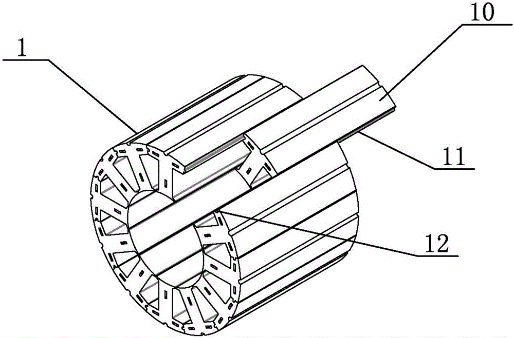
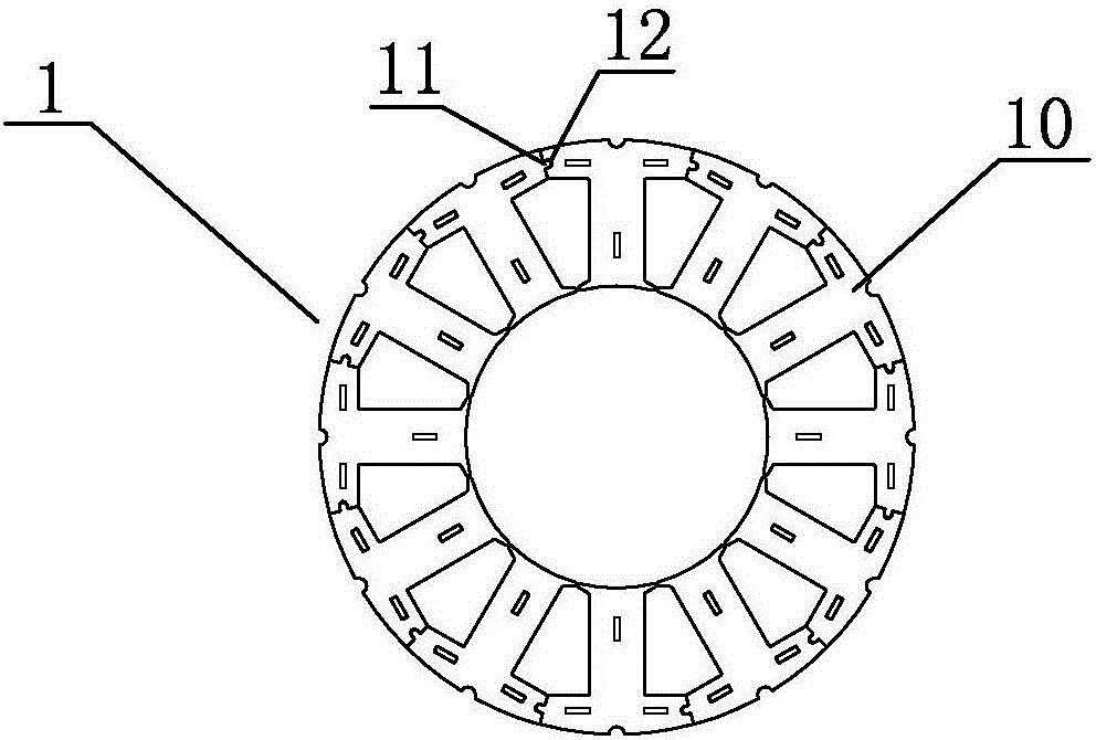
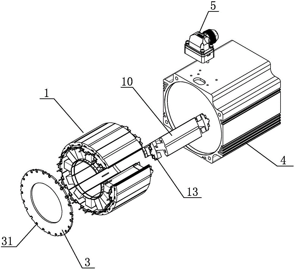
[0043] refer to Figure 1 to Figure 5 , the preferred embodiment provided by the present invention, a slotless assembled stator of a servo motor includes a motor casing 4 , a stator body 1 , a coil 2 and a PCB board 3 . The coil 2 is wound on the stator main body 1 , the PCB board 3 is fixed on one end of the stator main body 1 , and the stator main body 1 is installed in the motor casing 4 . An aviation connector 5 is also arranged outside the motor casing 4 .

[0044] The stator main body 1 is assembled from twelve T-shaped stator groups 10, and the angle between adjacent stator groups 10 is 30°. Corresponding ribs 11 and grooves 12 are respectively provided on the bonding surfaces of adjacent stator groups 10, and the stator groups 10 are assembled into a circular stator body 1 through self-riveting of the ribs 11 and grooves 12, Effectively control the verticality, parallelism and riveting force of the stator group 10. Coils 2 are respectively wound on the stator group ...


PUM


Abstract

The invention discloses a non-alveolar splicing stator of a servo motor. The non-alveolar splicing stator comprises a stator main body, coils and a printed circuit board (PCB), wherein the stator main body is formed by splicing a plurality of T-shaped stator groups, and the coils are respectively wound around the stator groups. The invention also discloses an assembly process of the non-alveolar splicing stator. The stator main body is formed by splicing the plurality of stator groups, the stator is not needed to be provided with alveolars, no distance is generated between pole numbers, the material utilization rate is effectively improved, the production cost is reduced, the motor torque is also increased, and the motor efficiency is improved; during assembly, wires can be directly wound around the stator groups in an external winding way, and the winding efficiency is improved; and during the assembly process, three processes of wire insertion, wire binding and shaping are omitted, the damage to an enameled wire is reduced, and the production efficiency is improved.

Description

technical field [0001] The invention relates to the field of motors, in particular to a slotless assembled stator of a servo motor and an assembly process thereof. Background technique [0002] The existing stator is formed by stacking punched silicon steel sheets, the stator has tooth grooves, and the distance between the poles is relatively large. During the assembly process of the stator, it is necessary to wind the enamelled copper wire into a specified coil in advance, and then insert it into the stator slot respectively, then perform wiring welding and wire binding according to the drawing, and finally slot the stator wedge after wiring, and immerse it in insulating varnish After being fully dipped in paint, take it out and bake it, and put it into the aluminum shell to complete the assembly of the stator. [0003] The existing stator structure and assembly process have the following disadvantages: [0004] 1) The stator is made of punched and buckled whole silicon s...

Claims


Application Information

Patent Timeline
Patent Type & Authority Applications(China)
IPC IPC(8): H02K1/14H02K15/02
CPCH02K1/14H02K15/022
Inventor 苏梓铭陈显超
Owner FOSHAN DEYI IND TECH CO LTD
Learn More