
Electrodeposition device

A technology of electrodeposition device and electrodeposition tank, which is applied in the direction of electrolysis process, electrolysis components, cells, etc., can solve the problems of uniformity of electrodeposition layer thickness, weak stirring effect, low deposition speed, etc., and achieve high-strength and uniform stirring effect , improved uniformity, and low-cost effects

Inactive Publication Date: 2016-07-13
HENAN POLYTECHNIC UNIV
View PDF4 Cites 5 Cited by
  • Summary
  • Abstract
  • Description
  • Claims
  • Application Information

AI Technical Summary

Problems solved by technology

Although air agitation can make the solution mix evenly, it is not suitable for the electrodeposition process that requires avoiding ion oxidation in the electrodeposition process, and air agitation cannot ensure a stable flow field on the surface of the cathode, so the electrodeposition composition and the thickness of the electrodeposition layer Uniformity will be affected; in the cathode moving stirring device, the cathode moving and stirring is easier to obtain a uniform mass transfer distribution on the cathode surface, but the intensity of the cathode moving and stirring is generally not high, and the global stirring effect on the entire electrodeposition tank is relatively low. The deposition rate is generally not high. The main reason is: the conventional cathode movement and stirring only rely on the shearing action between the workpiece (cathode) and the electrolyte to drive the movement of the electrolyte. If the workpiece cathode is in the shape of a flat sheet, its stirring effect is very weak. of
Although a variety of cathode stirring devices have been developed so far, they still have not achieved very satisfactory results.

Method used


Image

  • Electrodeposition device

Examples


Embodiment Construction

[0016] Combine below figure 1 The implementation of the present invention is described in further detail.

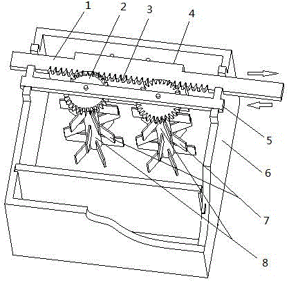
[0017] An electrodeposition device, comprising an electrodeposition tank 6, a cathode moving rod 1, and a cathode 4, is characterized in that: it includes a gear 2, a gear mounting rod 5, and a stirring paddle 7. The cathode 4 is installed on one side of the cathode moving rod 1; the cathode moving rod 1 is provided with a rack 3; the rack 3 is meshed with the gear 2; the gear 2 is rotatably fixed on the gear on the rod 5; the gear installation rod 5 is fixed on the electrodeposition tank 6; the stirring paddle 7 is coaxially installed on the gear shaft 8.

[0018] The cathode moving rod 1 is arranged in parallel on the electrodeposition tank 6 .

[0019] The cathode moving rod 1 can reciprocate under the action of external force.

[0020] The number of the gear shafts 8 can be increased or decreased according to the size and process requirements of the electrodeposit...


PUM


Abstract

The invention discloses an electrodeposition device which comprises an electrodeposition tank, a cathode, a cathode moving rod, a gear, a gear mounting rod and a stirring paddle.When the electrodeposition device works, the anode moving rod is in horizontal reciprocating motion under action of external force, a rack on the cathode moving rod drives the gear to be in forward and backward circular motion, and in this way, an electrolyte quickly flows under stirring action of the stirring paddle; the outer edge of the stirring paddle is close to the surface of the cathode, so that a flow field, on the surface of the cathode, of the electrolyte is relatively uniform, and uniformity of thickness of a cathode electrodeposition layer in the electrodeposition process is improved.

Description

technical field [0001] The invention relates to an electrodeposition device, in particular to a device for improving the thickness uniformity of a cathode electrodeposition layer. Background technique [0002] At present, in industrial production, in order to increase the electrodeposition speed and the ion diffusion speed in the solution, an electrolyte stirring device is often added. Electrodeposition (including electroplating, electroforming) electrolyte is mostly stirred by air stirring, liquid circulation stirring or cathode moving device. Although air agitation can make the solution mix evenly, it is not suitable for the electrodeposition process that requires avoiding ion oxidation in the electrodeposition process, and air agitation cannot ensure a stable flow field on the surface of the cathode, so the electrodeposition composition and the thickness of the electrodeposition layer Uniformity will be affected; in the cathode moving stirring device, the cathode moving ...

Claims


Application Information

Patent Timeline
Patent Type & Authority Applications(China)
IPC IPC(8): C25D21/10C25D17/00
CPCC25D17/00C25D21/10
Inventor 秦歌程丹佛刘建慧
Owner HENAN POLYTECHNIC UNIV
Learn More