Riverway floating oil removing device

A technology for oil slicks and river courses, which is applied in general water supply conservation, water conservancy projects, and cleaning of open water surfaces, etc. It can solve problems such as flow matching, heavy equipment, and insufficient draft of the bell mouth.

Active Publication Date: 2016-07-13
NINGBO DAHONGYING UNIV
View PDF4 Cites 1 Cited by
  • Summary
  • Abstract
  • Description
  • Claims
  • Application Information

AI Technical Summary

Problems solved by technology

In principle, there is nothing wrong with this collection method. The only thing that is difficult to guarantee is that the draft of the bell mouth cannot match the flow rate of the pump. If the draft is too shallow, the center of the bell mouth will form a vortex to suck in air and damage the pump; if If the draft is too deep, there will be more water and less oil in the oily sewage, which will lose the meaning of collecting oil slicks. Therefore, the use of this collection device has certain limitations. When the flow rate of the water pump is determined, the draft of the bell mouth is relatively determined. For still water, it is more convenient to use, but for more volatile water, the situation is completely different
Moreover, the water pump needs a motor for power, which has the problem of energy consumption, and the equipment is relatively heavy, so it is not suitable for long-term maintenance of large-area river water surfaces.

Method used


Image

  • Riverway floating oil removing device
  • Riverway floating oil removing device
  • Riverway floating oil removing device

Examples


Embodiment Construction

[0031] Hereinafter, embodiments of the present invention will be described in detail according to the accompanying drawings, so as to understand the technical content of the present invention more clearly.

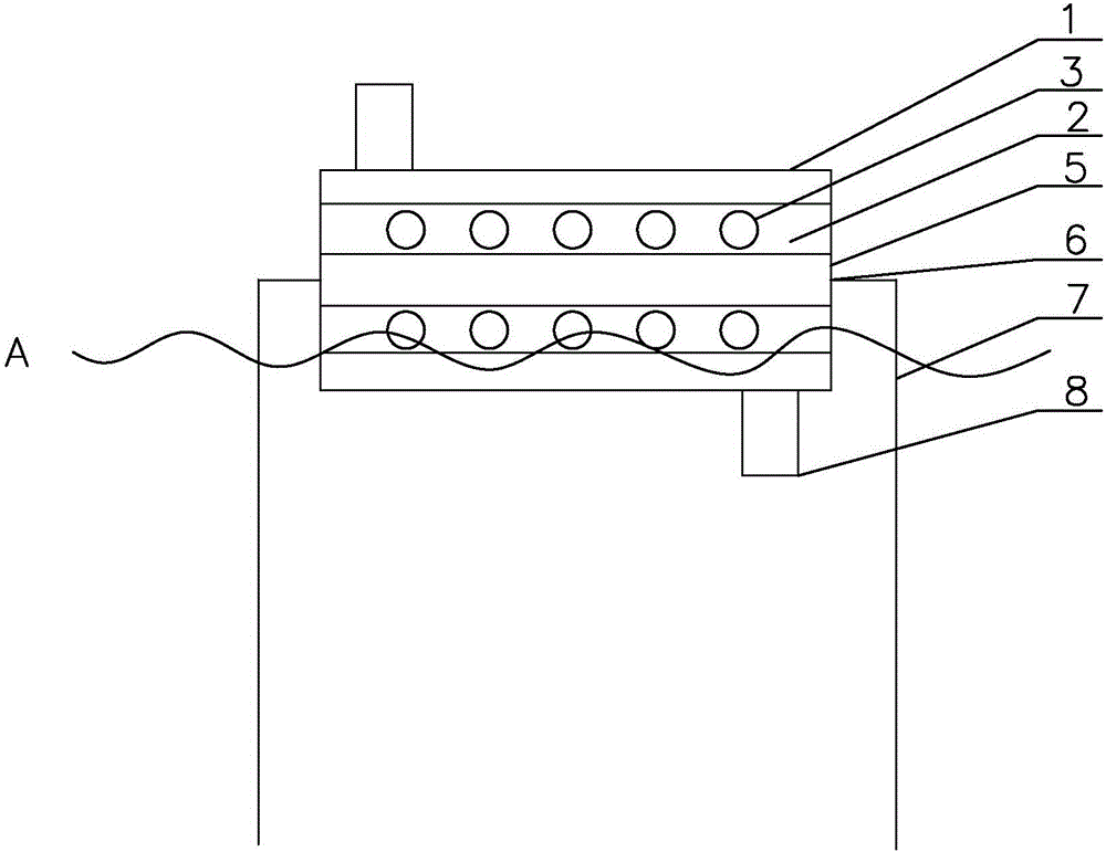
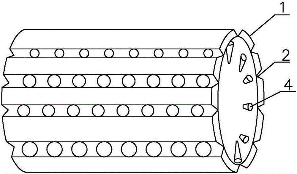
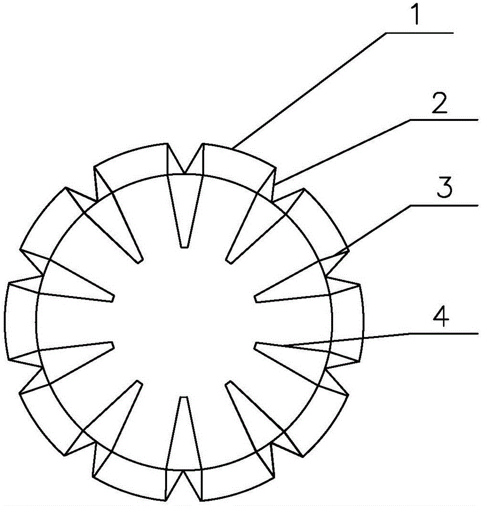
[0032] Such as Figure 1~3 As shown, in a specific embodiment of the river oil slick removal device of the present invention, a river channel oil slick removal device of the present invention includes a bracket 7, and a main body erected on the bracket 7 and movably connected with the bracket 7; wherein, The main body includes a hollow cylinder 1 , a sealing cover 5 and several blades 8 .

[0033] A plurality of grooves 2 are provided on the outer surface of the hollow cylinder 1 along the axial direction of the hollow cylinder 1, and several circular through holes 3 are provided at the bottom of each groove 2. The outer surface of the hollow cylinder 1 Both the surface and the surface of the groove 2 are covered with an oleophilic layer;

[0034] At the position corresp...


PUM


Abstract

The invention discloses a riverway floating oil removing device which comprises a bracket and a main body, wherein the main body is arranged on the bracket and moveably connected with the bracket and comprises a hollow cylinder, a sealing cover and a plurality of blades; grooves are formed in the axial direction in the outer surface of the hollow cylinder; through holes are formed in the bottoms of the grooves; the outer surface of the hollow cylinder and the surfaces of the grooves are all covered by oleophilic layers; one hollow conical cylinder extends inwards in the radial direction of each through hole in the inner wall of the hollow cylinder; the bottom of each hollow conical cylinder is arranged on the inner wall of the hollow cylinder; holes are formed in the bottom and the top of the hollow conical cylinder and are right aligned to the corresponding through holes; the sizes of the holes are not smaller than those of the corresponding through holes; sealing covers are arranged at two ends of the hollow cylinder; at least one of the sealing covers can be opened; blades protrude outwards in the radial direction on the outer surface of the hollow cylinder. The riverway floating oil removing device needs no power device, and is high in oil removing efficiency, simple in structure, low in price, moveable, convenient to use and low in maintenance cost.

Description

technical field [0001] The invention relates to the field of sewage treatment, in particular to a device for removing floating oil in a river course. Background technique [0002] With the rapid development of my country's economy, my country's water environment problems have become increasingly prominent, and urban and rural water environments have encountered unprecedented threats. Urban and rural rivers are severely degraded due to pollution and ecosystems. The water quality of the rivers is basically at the V or inferior V level. Most of the rivers are seriously polluted, eutrophic, lack of oxygen, black and smelly, resulting in a severe environmental and ecological situation. In addition, due to river shipping leakage or illegal discharge by coastal enterprises, more and more oil pollution is floating on the surface of the river. In recent years, oil pollution has always been a major problem in river treatment and management due to its difficulty in cleaning up, wide s...

Claims


Application Information

Patent Timeline
Patent Type & Authority Applications(China)
IPC IPC(8): E02B15/10
CPCE02B15/0835E02B15/103Y02A20/204
Inventor 丁洁琼蔡鲁祥
Owner NINGBO DAHONGYING UNIV
Why Eureka
Try Eureka