Eureka AIR delivers breakthrough ideas for toughest innovation challenges, trusted by R&D personnel around the world.

A multifunctional water mixing valve with an electric partition wall

A multi-functional, water-mixing valve technology, applied in multi-way valves, valve details, valve devices, etc., can solve the problems of low utilization rate of waterway box structure space, high cost of metal materials, and easy water pollution, etc. Easy to get dirt, high space utilization, uniform force effect

Active Publication Date: 2018-08-10
广东韦斯华电器发展有限公司
View PDF1 Cites 0 Cited by
  • Summary
  • Abstract
  • Description
  • Claims
  • Application Information

AI Technical Summary

Problems solved by technology

[0002] The water mixing valves installed in water heaters on the market are mostly made of metal, which is a conductive body. Once the water heater or water pipe is charged, it cannot avoid conduction to the user's body, causing electric shock accidents, and the cost of metal materials remains high. A water mixing valve of insulating material has appeared, such as the Chinese invention patent No. 03224738.9, which discloses a safety anti-electric mixing water valve. The water channel box in the water mixing valve is similar to a back shape. A problem: the first is that the structural space utilization rate of the back-shaped water channel box is low. If you want to form a sufficient length of electricity-isolated water channel, the volume of the back-shaped water channel box is bound to be large; the second is that the deposition surface of the water channel is flat. Facing directly, it is easy to accumulate dirt, and because it is inside the mixing valve, it cannot be disassembled and cleaned, so the water quality is easily polluted, and the pipes are also blocked due to scale formation

Method used


Image

  • A multifunctional water mixing valve with an electric partition wall
  • A multifunctional water mixing valve with an electric partition wall
  • A multifunctional water mixing valve with an electric partition wall

Examples


Embodiment 1

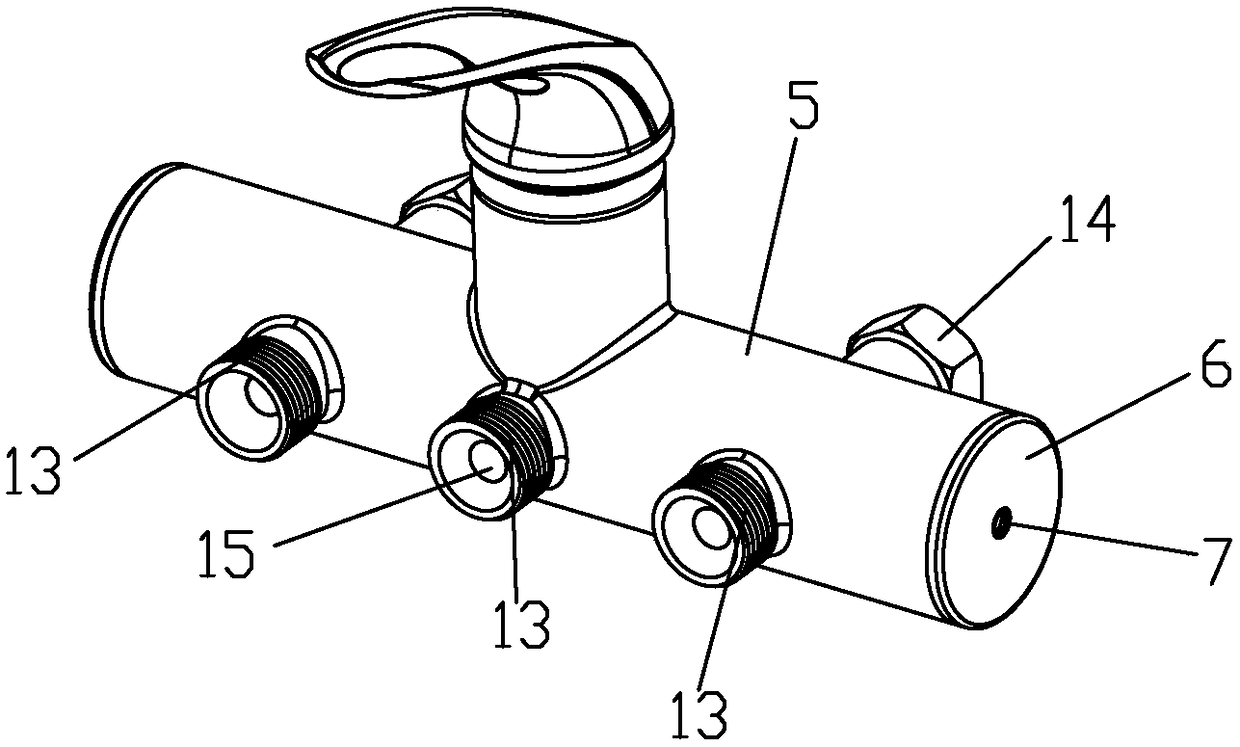
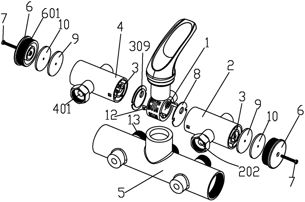
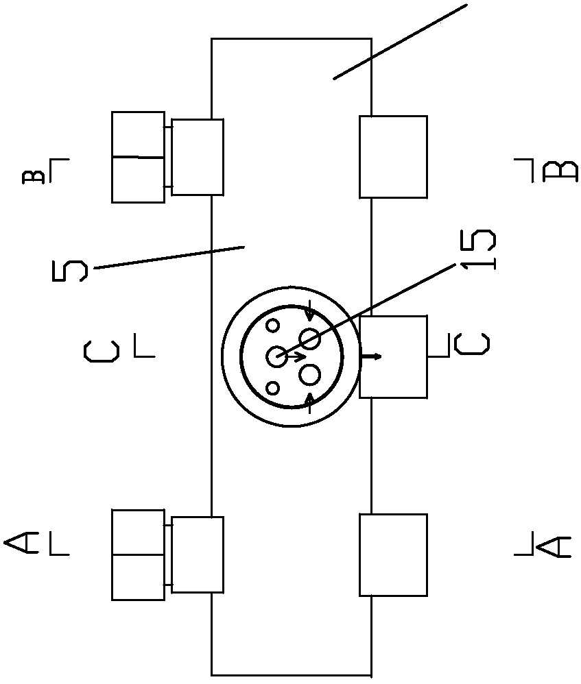
[0044] The working process of the first embodiment is as follows: Figure 5 As shown, the water flow enters the water inlet pipe 2 from the cold water inlet 201 and is divided into two branches, one of which goes half a circle in the forward direction into the outlet hole 202 of the inlet pipe and enters the water heater to be heated. A communicating hole 309 enters the valve core seat communicating body 1; the heated hot water enters the outlet pipe 4 from the inlet hole 401 of the outlet pipe, such as Figure 4 As shown, the hot water that enters the outlet pipe 4 is divided into two branches after traveling half a circle of the electricity isolation water channel. One branch flows out from the hot water outlet hole 402, and the other one completes the other half circle of the electricity isolation water channel and then passes through the first connecting hole. 309 enters the valve core seat communicating body 1 and mixes with cold water and flows out from the mixing water out...

Embodiment 2

[0045] The second embodiment is a two-layer electrical isolation water channel: such as Figure 7 to Figure 10 As shown, the water inlet pipe 2 and the water outlet pipe 4 are provided with an inner pipe 303 coaxially arranged with the water pipe to separate the water pipe cavity into an outer cavity and an inner cavity, on the inner wall of the water pipe and the outer wall of the inner pipe 303 There are a plurality of second partitions 305 radially dividing the outer cavity into a plurality of sub-outer cavities, and a plurality of blocks are radially arranged inside the inner tube 303 to divide the inner cavity into a plurality of sub-inner cavities. The third partition 307 of the cavity, the third partition 307 is fixed between the inner wall of the inner tube 303 and the central column 11, the two ends of the water inlet pipe 2 and the water outlet pipe 4 are sealed and further the second partition 305. The two ends of the third partition 307 are sealed, and at the end of...


PUM


Abstract

The invention discloses a multifunctional water mixing valve with an electricity isolating wall. The multifunctional water mixing valve is technically characterized by comprising a valve element base communicating body, a water inlet pipe and a water outlet pipe, wherein the water inlet pipe and the water outlet pipe are arranged on the valve element base communicating body and communicated with the valve element base communicating body. The water inlet pipe and the water outlet pipe are round pipes. Multiple partition plates for dividing cavities of the water pipes into axial electricity isolating water channels detouring many times are arranged in the water inlet pipe and the water outlet pipe. As the water outlet pipe and the water inlet pipe are round, 360-degree space of the round pipes is utilized fully, and the space utilization rate is very high; in addition, at least one of deposition faces of the electricity isolating water channels is an arc face, compared with straight deposition faces, dirt on the arc faces is washed away more easily, accordingly, dirt accumulation is not caused easily, and the water channels can not be blocked easily.

Description

【Technical Field】 [0001] The invention relates to a water mixing valve, in particular to a multifunctional water mixing valve with an electrical isolation wall. 【Background technique】 [0002] The water mixing valve installed in the current water heaters on the market is mostly made of metal, which is a conductive body. Once the water heater or water pipe is charged, it cannot be prevented from being transmitted to the human body, causing electric shock accidents, and the cost of metal materials remains high. Insulating water mixing valves have appeared, such as the Chinese invention patent No. 03224738.9, which discloses a safe anti-electric water mixing valve. The water channel box in the water mixing valve is similar to the back shape, and the water channel box has two A problem: The first is that the space utilization of the water channel box structure of the back shape is low. If you want to form a sufficient length of electricity-isolated water channel, the volume of the wa...

Claims


Application Information

Patent Timeline
Patent Type & Authority Patents(China)
IPC IPC(8): F16K11/02F16K27/00F16K27/12
CPCF16K11/02F16K27/00F16K27/12
Inventor 杨茂兴韦红陵
Owner 广东韦斯华电器发展有限公司
Why Eureka
Eureka Blog
Learn More