Induction cooker

A technology of induction cooker and circuit board, which is applied in the field of induction cooker, can solve problems such as adverse effects of work performance, reduction of comfort in use, short circuit of circuit board, etc., and achieve the effects of eliminating electrical safety hazards, avoiding noise, and improving heat dissipation effect

Inactive Publication Date: 2016-07-13
GREE ELECTRIC APPLIANCES INC
View PDF0 Cites 0 Cited by
  • Summary
  • Abstract
  • Description
  • Claims
  • Application Information

AI Technical Summary

Problems solved by technology

In order to dissipate heat from the above-mentioned coil disks to prevent performance degradation and electrical safety due to overheating of the coil disks and other electronic components inside the induction cooker, and at the same time to dissipate heat from large calorific components such as bridge stacks, IGBTs, and transformers on the circuit board to ensure normal operation To work, a cooling fan needs to be installed in the furnace cavity of the existing induction cooker. Correspondingly, an air inlet and an air outlet need to be provided on the base of the induction cooker. After the device absorbs heat, it turns into hot air and is discharged from the air outlet. The air inlet and air outlet are generally made into a grid shape to facilitate the passage of air flow and prevent the user's fingers from passing through. However, the disadvantage is that the overflow of the pot overflows Soup and insects can enter the furnace cavity through the grid-shaped air inlet and outlet, which may easily cause electrical safety hazards such as short circuit of the circuit board; at the same time, the operation of the cooling fan will inevitably produce a certain amount of operating noise, which reduces the comfort of the user Moreover, with the increase of the running time of the cooling fan, the oil fume and dust entering the furnace cavity with the air flow will also increase, resulting in dirt in the furnace cavity, which is not only difficult to clean, but also affects the work of various components in the furnace cavity. Bad performance

Method used


Image

  • Induction cooker
  • Induction cooker
  • Induction cooker

Examples


Embodiment Construction

[0021] In order to make the object, technical solution and advantages of the present invention clearer, the induction cooker of the present invention will be further described in detail below in conjunction with the accompanying drawings and embodiments. It should be understood that the specific embodiments described here are only used to explain the present invention, not to limit the present invention.

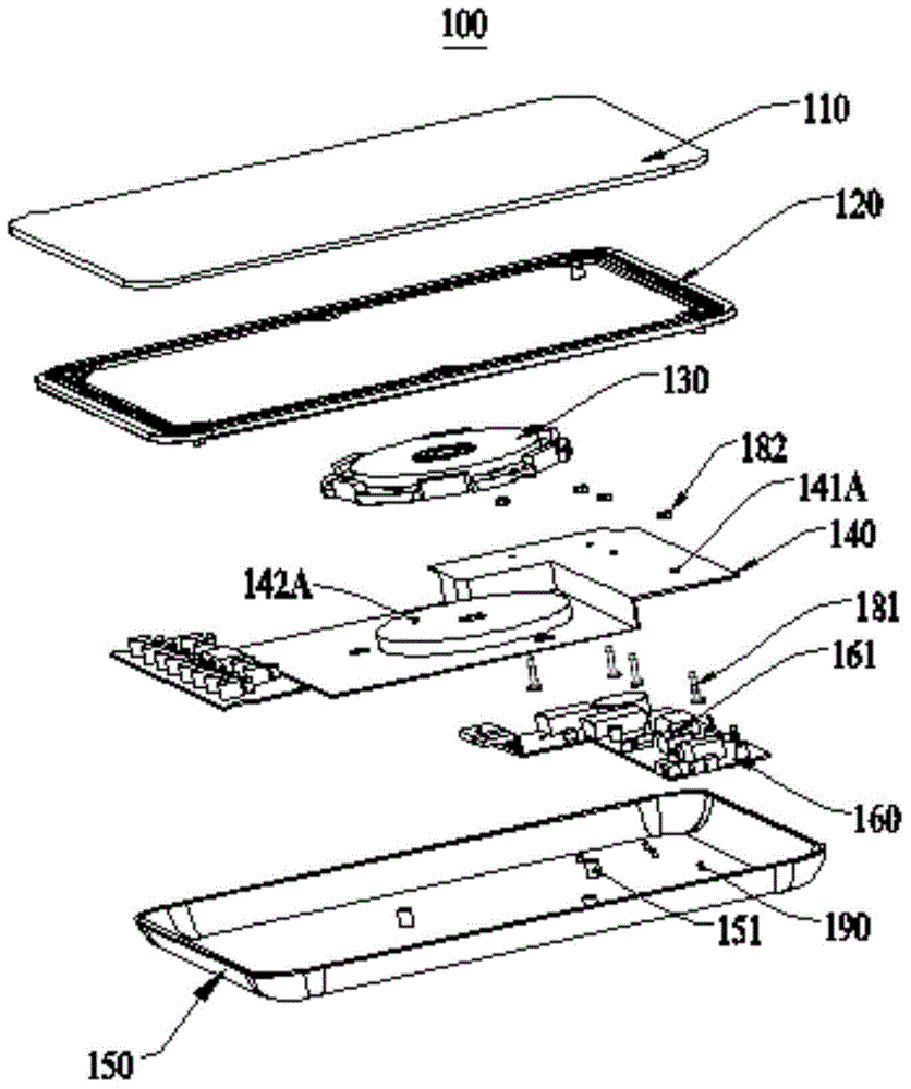
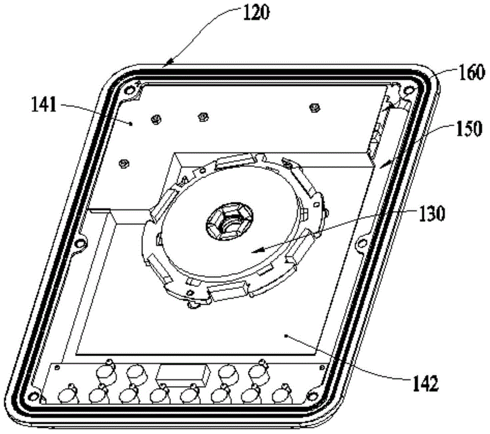
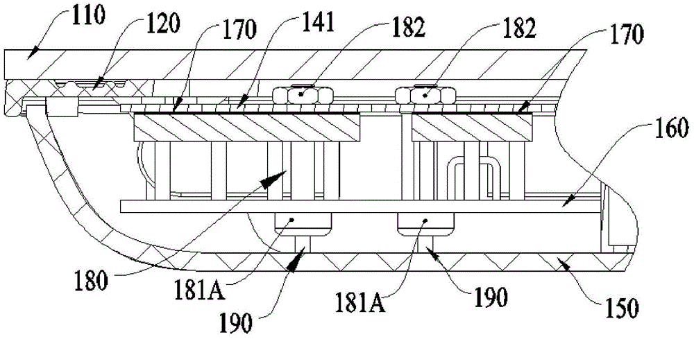
[0022] figure 1 , 2 and 3 show a preferred embodiment of the induction cooker of the present invention, the induction cooker 100 includes a base 150, a circuit board 160, a large calorific value component 161, a coil plate 130 and a heat conducting plate 140, the circuit board 160, the coil plate 130 and a heat conducting plate 140 is installed in the base 150 , and a large heating element 161 is installed on the circuit board 160 . Both the base 150 and the heat conducting plate 140 are made of metal material or a good thermal conductor material, and the thermally conduct...


PUM


Abstract

The invention discloses an induction cooker, comprising a base, a circuit board, a high-heat-production component and a coil disc.The circuit board and the coil disc are mounted in the base, the high-heat-production component is mounted on the circuit board, and the base and a heat guide board are made of a metal material or a good heat conduction material; the heat guide board is mounted in the base, a heat-conducting insulating material is disposed between the high-heat-production component and the heat guide plate, and the heat guide plate is in heat conductive connection with the base.In the induction cooker, the heat guide plate and the base made of the metal material or the high heat conduction material are used to cool the coil disc and the high-heat-production component; therefore, the induction cooker of the invention requires no cooling fan, thus reducing operation noise, improving safety of use and providing good cooling effect.

Description

technical field [0001] The invention relates to a kitchen appliance, especially an induction cooker. Background technique [0002] Existing induction cookers mainly rely on the work of the coil plate to heat pots and the like. The coil plate is not only the heat source for the cooker, but also the heat source for heating up other electronic components inside the induction cooker when the induction cooker is working. Moreover, when the existing induction cooker uses an alternating magnetic field to generate eddy currents at the bottom of the pot to heat the food, its working principle is: rely on the bridge stack on the circuit board to rectify and then pass through the power transistor (IGBT) to continuously turn on and off To generate an alternating magnetic field, therefore, the bridge stack and IGBT, as well as the transformer on the circuit board that supplies power to them, will generate a lot of heat during operation. In order to dissipate heat from the above-mentione...

Claims


Application Information

Patent Timeline
Patent Type & Authority Applications(China)
IPC IPC(8): F24C7/06
Inventor 潘海元
Owner GREE ELECTRIC APPLIANCES INC
Why Eureka
Try Eureka