
Method for obtaining included angel between a lens plane and an image sensor plane

A sensor and plane technology, applied in the field of testing the angle between the lens plane and the image sensor plane, can solve the problem of time-consuming

Active Publication Date: 2016-07-13
NINGBO SUNNY OPOTECH CO LTD
View PDF6 Cites 6 Cited by
  • Summary
  • Abstract
  • Description
  • Claims
  • Application Information

AI Technical Summary

Problems solved by technology

[0004] Traditionally, the defocus curve is used to calculate the Tilt between the Lens plane and the Sensor plane. This method requires the motor to run a certain stroke to obtain multiple images for calculation, which takes a long time. Therefore, the problem to be solved by the present invention is Quickly and accurately obtain the Tilt between the Lens plane and the Sensor plane

Method used


Image

  • Method for obtaining included angel between a lens plane and an image sensor plane
  • Method for obtaining included angel between a lens plane and an image sensor plane
  • Method for obtaining included angel between a lens plane and an image sensor plane

Examples


Embodiment Construction

[0024] The following description serves to disclose the present invention to enable those skilled in the art to carry out the present invention. The preferred embodiments described below are only examples, and those skilled in the art can devise other obvious variations. The basic principles of the present invention defined in the following description can be applied to other embodiments, variations, improvements, equivalents and other technical solutions without departing from the spirit and scope of the present invention.

[0025] In the technical solution provided by the present invention, the components included in the Tilt test include: a standard plate, a light source, an image acquisition device, a module and corresponding Tilt test software.

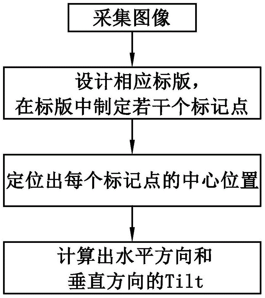
[0026] Such as figure 1 and Figure 4 Shown, the present invention is implemented according to the following steps:

[0027] (1) Acquisition of images

[0028] Initialize the image sensor, turn on the module, and use the imag...


PUM


Abstract

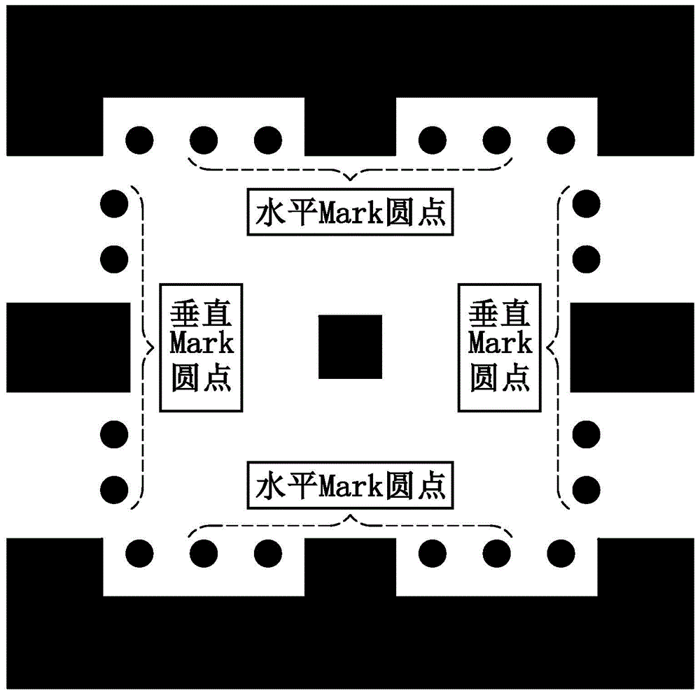
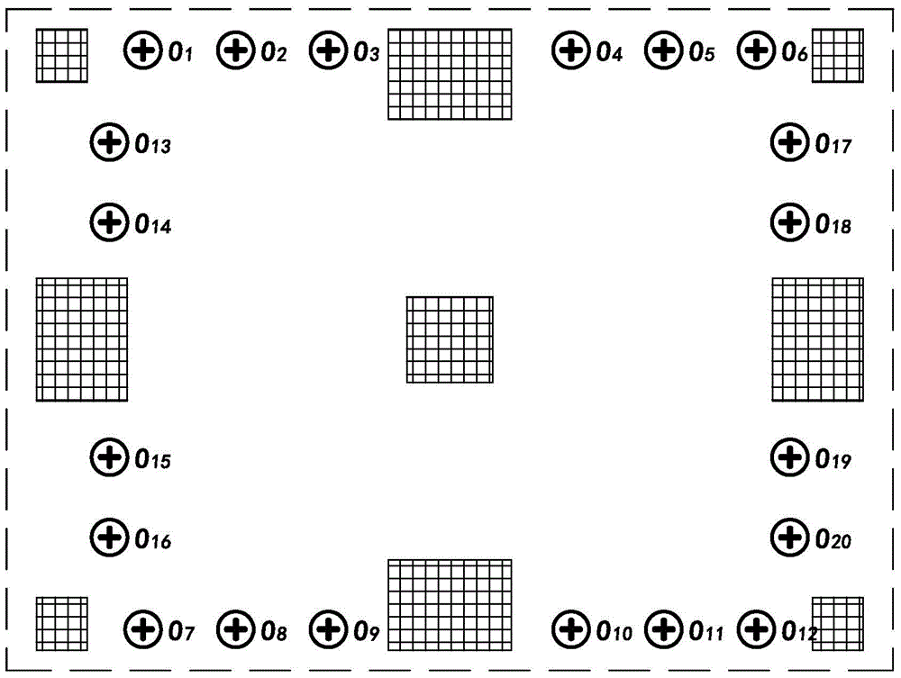
The invention provides a method for obtaining an included angle between a lens plane and an image sensor plane. The method includes steps of 1, collecting an image by an image collecting device; 2, designing a mark board and marking a plurality of mark points in the mark board, wherein the size of the mark board is equal to the image; 3, positioning the central position of the marking points by adopting image segmenting, detecting and identifying technology; and 4, calculating the included angle in the horizontal direction and the vertical direction between the lens plane and the sensor plane through included angle testing software. Two mark points are connected so as to form a straight line, an included angle between two symmetric straight lines in the horizontal direction and an included angle between two symmetric straight lines in the vertical direction are calculated. The Tilt in the horizontal direction and the Tilt in the vertical direction can be obtained through included angles between straight lines. Finally, the included angle between the lens plane and the sensor plane is detected. The method is low in time consumption and high in precision. Module quality can be reflected accurately.

Description

technical field [0001] The invention relates to the field of testing methods for the angle (Tilt) between a lens (Lens) plane and an image sensor (Sensor) plane, in particular to a method for quickly obtaining the Tilt between a Lens plane and a Sensor plane. Background technique [0002] In recent years, with the increasingly fierce competition in the mobile phone lens market and the development of chip technologies such as CCD or CMOS, the pixel size of the chip is getting smaller and smaller, and the imaging quality requirements of the matching optical system are also getting higher and higher. It promotes the research and development of the camera, and makes the camera lens develop rapidly in the field of miniaturization and high pixel, so as to meet people's demand for image quality. [0003] With the rapid development of the mobile phone industry, the module manufacturing process requirements have been improved accordingly. Modern mobile phone camera modules have small...

Claims


Application Information

Patent Timeline
IPC IPC(8): G01B11/26
Inventor 丁亮廖海龙张宝忠王明珠
Owner NINGBO SUNNY OPOTECH CO LTD
Learn More