
Layout structure of combined photomask as well as formation method and application method for layout structure

A technology of layout structure and photomask, which is applied in the photoplate making process of the pattern surface, the original for photomechanical processing, optics, etc., can solve the problem of not being able to obtain rectangular holes or rectangular islands, and achieve simple structure and increase the number of windows , to meet the effect of resolution

Inactive Publication Date: 2016-07-13
WUHAN XINXIN SEMICON MFG CO LTD
View PDF4 Cites 12 Cited by
  • Summary
  • Abstract
  • Description
  • Claims
  • Application Information

AI Technical Summary

Problems solved by technology

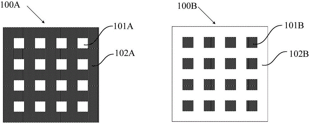
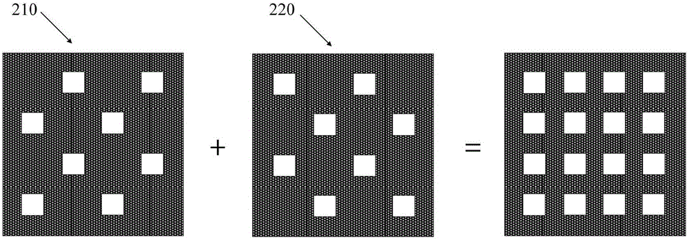
Using the layout structure of the combined photomask to carry out photolithography process can form rectangular holes or rectangular islands on the semiconductor substrate, so as to solve the problem that the rectangular holes or rectangular islands as designed in the layout cannot be obtained in the prior art due to the optical proximity effect The problem

Method used


Image

  • Layout structure of combined photomask as well as formation method and application method for layout structure
  • Layout structure of combined photomask as well as formation method and application method for layout structure
  • Layout structure of combined photomask as well as formation method and application method for layout structure

Examples


Embodiment Construction

[0047]The layout structure of a combined photomask proposed by the present invention and its forming method, as well as the application of the combined photomask in semiconductor manufacturing, will be described in further detail below with reference to the accompanying drawings and specific embodiments. Advantages and features of the present invention will be apparent from the following description and claims. It should be noted that all the drawings are in a very simplified form and use imprecise scales, and are only used to facilitate and clearly assist the purpose of illustrating the embodiments of the present invention.

[0048] The invention provides a layout structure of a combined mask, which can form a rectangular hole or a rectangular island on a semiconductor substrate even under the influence of the optical proximity effect; When hole arrays or arrays are used, the resolution required for dense graphics can be met by using the combined mask provided by the present ...


PUM


Abstract

The invention provides a layout structure of a combined photomask as well as a formation method and an application method for the layout structure. The layout structure of the combined photomask comprises a first layout and a second layout, wherein the first layout is provided with first line strips arranged in parallel at intervals; and the second layout is provided with second line strips arranged at intervals and perpendicular to the first line strips. With the adoption of the layout structure of the combined photomask, provided by the invention, rectangular holes and rectangular islands can be formed by changing a technological process. In addition, the layout structure of the combined photomask, adopted by the invention, is relatively simple in structure and has a relatively large photoetching process window, so that the resolution required for making high-density hole arrays or island arrays can be met.

Description

technical field [0001] The invention relates to the technical field of semiconductor manufacturing, in particular to a layout structure of a combined photomask and a forming method thereof, and an application method of the combined photomask in semiconductor manufacturing. Background technique [0002] Integrated circuit manufacturing technology is a complicated process, and the technology is updated very quickly. A key parameter that characterizes integrated circuit manufacturing technology is the minimum feature size, that is, critical dimension (critical dimension CD). The size of the critical dimension has developed from the initial 125 μm to the current 0.13 μn, or even smaller. It is precisely because of the reduction of the critical dimension that the It is possible to place millions of devices on each chip. However, on the other hand, the window of the photolithography process is getting smaller and smaller. [0003] For example, when making a hole (Hole) array or ...

Claims


Application Information

Patent Timeline
IPC IPC(8): G03F1/36G03F1/68
CPCG03F1/36G03F1/68
Inventor 曹清晨
Owner WUHAN XINXIN SEMICON MFG CO LTD
Learn More