Check patentability & draft patents in minutes with Patsnap Eureka AI!

Constant-current circuit and sensor device having this

A technology of constant current circuit and amplifying circuit, which can be used in instruments, regulating electrical variables, control/regulating systems, etc., and can solve problems such as range limitation and limitation

Inactive Publication Date: 2016-07-13
ALPS ALPINE CO LTD
View PDF7 Cites 2 Cited by
  • Summary
  • Abstract
  • Description
  • Claims
  • Application Information

AI Technical Summary

Problems solved by technology

Therefore, the output voltage range is limited to a voltage lower than the power supply voltage VDD by a voltage equivalent to the overdrive voltage corresponding to two transistors (M12, M14).
However, the so-called output voltage range is limited, which means that the range of current that can be supplied to the load RL of the same impedance is limited.

Method used


Image

  • Constant-current circuit and sensor device having this
  • Constant-current circuit and sensor device having this
  • Constant-current circuit and sensor device having this

Examples


no. 1 Embodiment approach

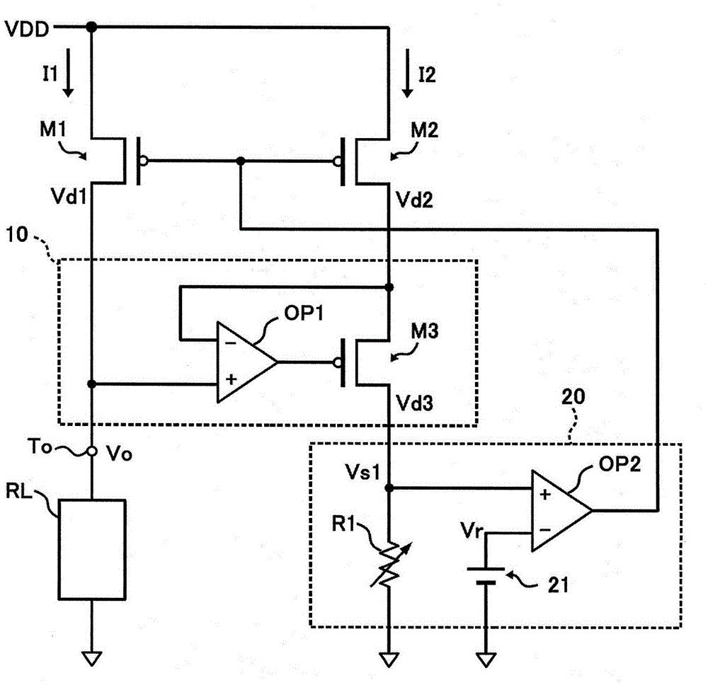
[0035] figure 1 It is a figure which shows an example of the structure of the constant current circuit concerning 1st Embodiment.

[0036] figure 1 The illustrated constant current circuit includes PMOS-type first transistor M1 and second transistor M2 , a voltage control circuit 10 , and a current control circuit 20 .

[0037] The first transistor M1 and the second transistor M2 constitute a current mirror circuit. The sources of the first transistor M1 and the second transistor M2 are connected to each other, and their gates are connected to each other. The sources of the first transistor M1 and the second transistor M2 are connected to the power supply voltage VDD, and a control signal of the current control circuit 20 described later is input to the gates thereof.

[0038] The drain of the first transistor M1 is connected to a current output terminal To, and a load RL is connected between the output terminal To and ground. The first current I1 flowing through the fir...

no. 2 Embodiment approach

[0057] Next, a second embodiment of the present invention will be described.

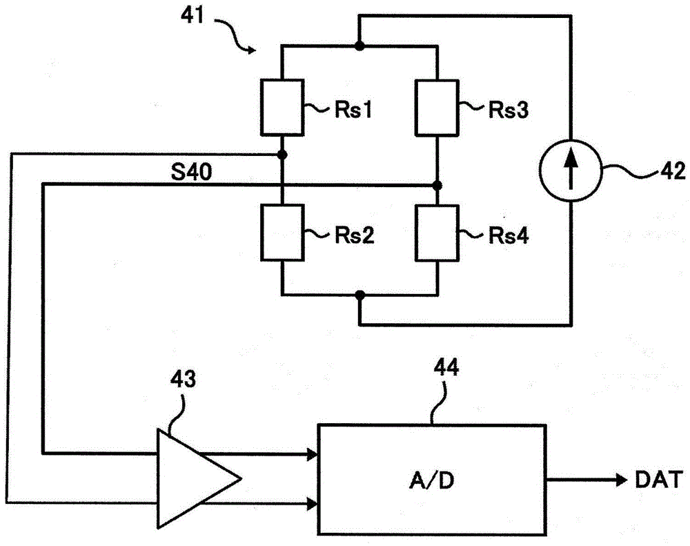
[0058] figure 2 It is a figure which shows an example of the structure of the sensor apparatus concerning 2nd Embodiment. figure 2 The sensor device shown is, for example, a pressure sensor with a bridge circuit 41 , a constant current circuit 42 , an amplifier circuit 43 and an AD converter 44 .

[0059] The bridge circuit 41 is a Wheatstone bridge circuit configured using the resistive sensor elements Rs1 to Rs4 , and outputs a detection signal S40 corresponding to changes in the resistance values ​​of the resistive sensor elements Rs1 to Rs4 . The resistive sensor elements Rs1 to Rs4 are, for example, piezoresistive elements, and the resistance value changes according to pressure.

[0060] The constant current circuit 42 supplies a constant current to the bridge circuit 41 . Accordingly, the detection signal S40 of the bridge circuit 41 becomes a voltage signal indicating a change in the res...


PUM


Abstract

The invention provides a constant-current circuit with wide output voltage range. A first transistor (M1) and a second transistor (M2) form a current mirror circuit. A second current (I2) flowing in the second transistor (M2) is kept constant by a current control circuit (20). Therefore, a first current (I1), to be output to a load (RL), in the first transistor (M1) is kept at a constant value responsive to the second current (I2) in the second transistor (M2). Since a drain voltage (Vd2) in the second transistor (M2) is controlled so as to become equal to a drain voltage (Vd1) in the first transistor (M1), even if a voltage (Vo) at an output terminal (To) changes in response to a change in the impedance of the load (RL), a ratio between the first current (I1) and the second current (I2) becomes substantially equal to a size ratio K between the first transistor (M1) and the second transistor (M2). That is, the first transistor (M1) and the second transistor (M2) precisely operate as a current mirror circuit.

Description

technical field [0001] The present invention relates to a constant current circuit for supplying a constant current to a load and a sensor device having the same. Background technique [0002] A circuit that uses a current mirror circuit to supply a constant current to a load is generally known. In a normal current mirror circuit, there is a difference between the voltage of one transistor through which a load current flows (drain-source voltage in the case of a MOS transistor) and the voltage of the other transistor through which a constant current flows. , so according to this voltage difference, the load current changes. For this reason, when high constant current performance is required, a cascode-connected transistor is generally added. [0003] image 3 It is a diagram showing a conventional example of a constant current circuit provided with cascode-connected transistors. image 3 The shown constant current circuit has PMOS transistors M11-14 and a constant current ...

Claims


Application Information

Patent Timeline
IPC IPC(8): G05F1/565
CPCG05F3/267G05F1/565
Inventor 浅尾阳筱井洁
Owner ALPS ALPINE CO LTD
Features
  • R&D
  • Intellectual Property
  • Life Sciences
  • Materials
  • Tech Scout
  • Unparalleled Data Quality
  • Higher Quality Content
  • 60% Fewer Hallucinations
Learn More