Level shifter for array substrate gate driving circuit

A gate drive circuit and level shifter technology, applied in instruments, static indicators, etc., can solve the problems of excessive output current ripple of level shifters, poor electromagnetic interference effect, and too fast voltage change.

Active Publication Date: 2016-07-13
TCL CHINA STAR OPTOELECTRONICS TECH CO LTD
View PDF7 Cites 12 Cited by
  • Summary
  • Abstract
  • Description
  • Claims
  • Application Information

AI Technical Summary

Problems solved by technology

[0004] At present, the difference between the maximum voltage and the minimum voltage of several voltages used in the GOA circuit will be 35V or even greater during the process of high and low changes. Then, the level sh

Method used


Image

  • Level shifter for array substrate gate driving circuit
  • Level shifter for array substrate gate driving circuit

Examples


Embodiment Construction

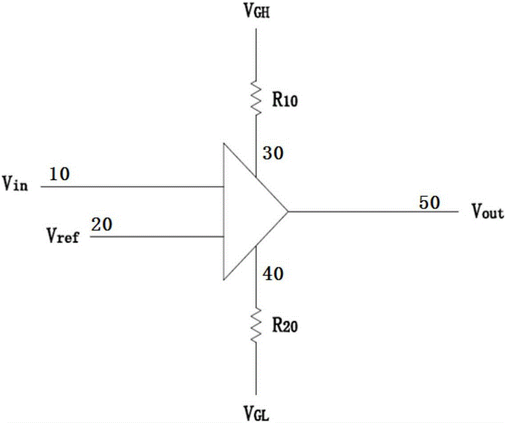
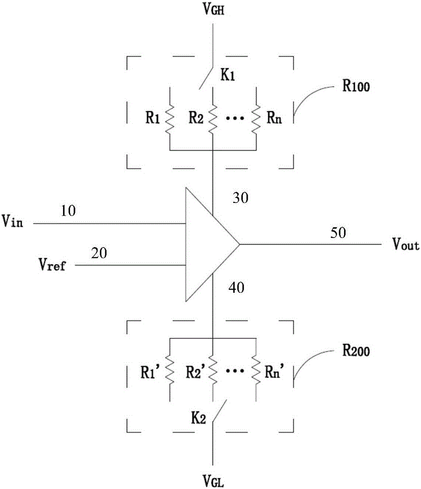
[0019] Refer below Figure 1 to Figure 2 A level shifter for an array substrate gate driving circuit according to an embodiment of the present invention is described.

[0020] figure 1 A schematic circuit diagram showing a level shifter used in an array substrate gate driving circuit according to an embodiment of the present invention. refer to figure 1 , an embodiment of the present invention proposes a level shifter for an array substrate gate drive circuit, comprising: a first input terminal 10, a second input terminal 20, a third input terminal 30, a fourth input terminal 40 and The output terminal 50 also includes: a first resistor R 10 and a second resistor R 20 ; The first input terminal 10 receives the logic control signal V in ; The second input terminal 20 receives the reference voltage V ref ; the first resistor R 10 One terminal receives the first voltage V GH , the third input 30 is connected to the first resistor R 10 the other end of the first resistor ...


PUM


Abstract

The invention provides a level shifter for an array substrate gate driving circuit. The level shifter comprises a first input end, a second input end, a third input end, a fourth input end, an output end, a first resistor and a second resistor; the first input end receives a logic control signal; the second input end receives a reference voltage; one end of the first resistor receives a first voltage, and the third input end is connected to the other end of the first resistor so as to receive the voltage from the first resistor; one end of the second resistor receives a second voltage, and the fourth input end is connected to the other end of the second resistor so as to receive the voltage from the second resistor; the output end alternatively outputs the voltage received by the third input end and the voltage received by the fourth input end according to the logic control signal and the reference voltage. According to the level shifter, variable resistors are additionally arranged to control the slope of output voltage variation of the output end, a level shifter output current ripple is reduced, and meanwhile the effect of reducing electromagnetic interference is achieved.

Description

technical field [0001] The present invention generally relates to the technical field of liquid crystal display, and more specifically, relates to a level shifter used in an array substrate gate drive circuit. Background technique [0002] Gate Driver On Array (GOA) technology is a technology that manufactures the gate scanning drive circuit of thin film transistor (ThinFilm Transistor, TFT) on the array substrate to replace the driver chip made of external silicon chips. The gate voltage of each row of TFTs in the liquid crystal display can be provided by a GOA circuit. In the GOA circuit, a level shifter (LevelShifter) is generally used to generate a clock control signal to control each row of TFTs to be turned on or off. [0003] Existing level conversion circuits for GOA architecture liquid crystal displays usually include: a timing controller located on the circuit driver board, which is used to generate and send logic control signals (LogicControl); a timing controller...

Claims


Application Information

Patent Timeline
IPC IPC(8): G09G3/36
CPCG09G3/36G09G3/3677
Inventor 张先明曹丹
Owner TCL CHINA STAR OPTOELECTRONICS TECH CO LTD
Why Eureka
Try Eureka