Lift installation

A technology for equipment and elevators, applied in elevators, transportation and packaging in buildings, etc., can solve problems such as large space requirements and high consumption, and achieve the effects of reduced requirements, low cost, and reduced load

Inactive Publication Date: 2016-07-13
INVENTIO AG
View PDF7 Cites 2 Cited by
  • Summary
  • Abstract
  • Description
  • Claims
  • Application Information

AI Technical Summary

Problems solved by technology

This results in overall high complexity in terms of realization, a large space requirement and associated expenditures

Method used


Image

  • Lift installation
  • Lift installation
  • Lift installation

Examples


Embodiment Construction

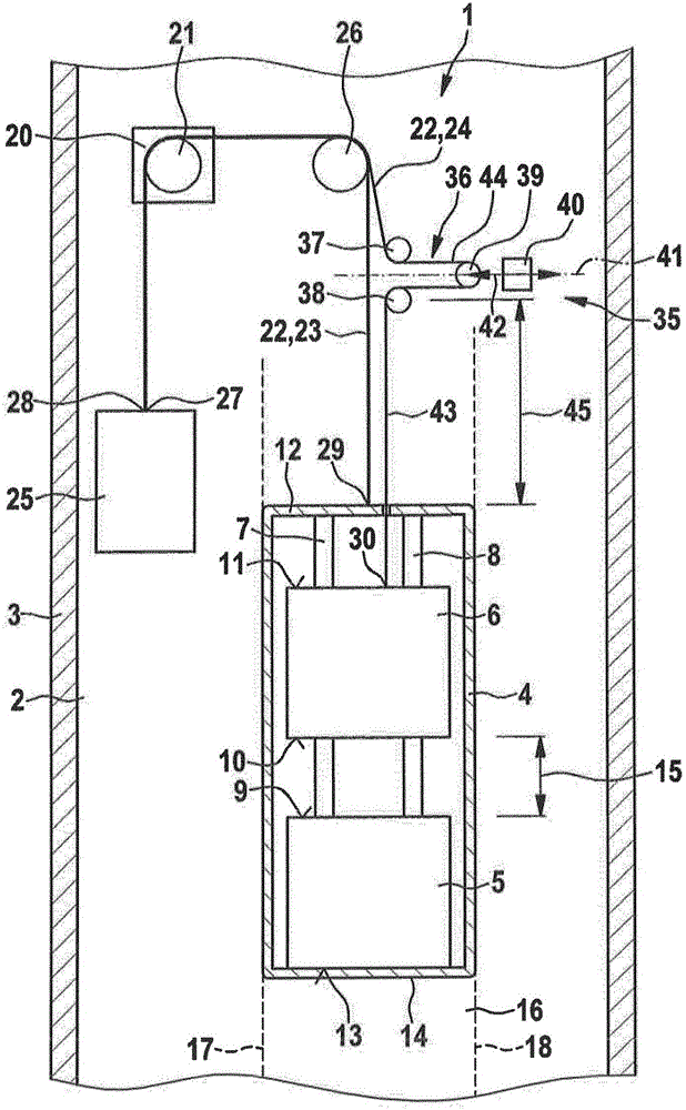
[0028] figure 1 An elevator installation 1 in an elevator shaft 2 of a building 3 is shown in a simplified schematic diagram corresponding to a first exemplary embodiment of the invention. The elevator installation 1 has an elevator cage frame 4 , a first elevator cage 5 and a second elevator cage 6 . The elevator cages 5 , 6 are arranged in the elevator cage frame 4 here. In the present exemplary embodiment, the first elevator car 5 and also the second elevator car 6 are arranged inside the elevator car frame 4 . In this case, the first elevator car 5 is fixedly connected to the elevator car frame 4 . The first elevator car 5 is thus arranged in a stationary manner relative to the elevator car frame 4 .

[0029] The elevator car frame 4 has guide rails 7 , 8 in the present exemplary embodiment. In the present exemplary embodiment, the second elevator car 6 is movable in the elevator car frame 4 . In this case, a certain safety distance is provided between the upper side ...


PUM


Abstract

A lift installation (1) comprises a first lift car (5), a second lift car (6), a drive-machine unit (20) and a plurality of traction means (22) running over a driving sheave (21) of the drive-machine unit (20). The lift cars (5, 6) here can be displaced one above the other by the drive-machine unit (20), using the traction means (22), in a passageway (16) provided for the joint travel of the lift cars (5, 6). The traction means (20) are divided up into a first traction-means assembly (23) and a second traction-means assembly (24). Also provided is an adjustment mechanism (35) which is in a fixed position relative to the passageway (16) and interacts with the second traction-means assembly (24) between the driving sheave (21) and the second lift car (6). The adjustment mechanism (35) here interacts with the second traction-means assembly (24) such that it is possible to vary a distance (15) between the lift cars (5, 6). The lift installation (1) is distinguished in that the distance (15) can be adjusted independently of the driving sheave (21), in particular even with the driving sheave (21) at a standstill. It is specifically possible for the adjustment mechanism (35) to have a roller arrangement (36), wherein an adjustable roller (39) of the roller arrangement (36) can be adjusted by an adjustment drive (40) in order to vary the length (45) of a portion (43) of the second traction-means assembly (24) between the adjustment mechanism (35) and the second lift car (6).

Description

technical field [0001] The invention relates to an elevator installation having a first elevator cage and at least one second elevator cage, the elevator installation being preferably arranged in an elevator cage frame of the elevator installation. The invention relates in particular to the field of elevator installations designed as so-called double-deck elevator installations. Background technique [0002] An elevator with two elevator cars is known from WO 2005 / 014461 A1, wherein the two elevator cars are coupled to one another in such a way that the two elevator cars can move together in the elevator shaft. In this case, the vertical spacing between the two elevator cars can be adjusted by means of a movement of at least one elevator car relative to the other elevator car. Use an adjustment rope for this. In this case, the ends of the adjustment ropes are fastened to the shaft bottom. A counterweight is suspended from the other end of the adjustment rope. In addition...

Claims


Application Information

Patent Timeline
Patent Type & Authority Applications(China)
IPC IPC(8): B66B11/02
CPCB66B11/022B66B11/02B66B11/0266B66B11/028
Inventor 阿德里安·斯坦内尔克里斯多夫·舒勒尔尼古拉斯·格雷莫雷内·斯特雷伯尔乌尔斯·沙夫豪泽尔马赛尔·尼可尔
Owner INVENTIO AG
Why Eureka
Try Eureka