Ultrasonic cleaning machine

A cleaning machine and ultrasonic technology, applied in cleaning methods and utensils, cleaning methods using liquids, chemical instruments and methods, etc., can solve the problems of low space utilization rate and low energy utilization rate, so as to improve energy utilization rate, The effect of improving heating efficiency

Inactive Publication Date: 2016-07-20
ANHUI LVJIAN DETECTION TECH SERVICE CO LTD
View PDF8 Cites 5 Cited by
  • Summary
  • Abstract
  • Description
  • Claims
  • Application Information

AI Technical Summary

Problems solved by technology

[0004] The technical problem to be solved by the present invention is: aiming at the problems of low energy utilization rate and low space utilization rate of the existing ultrasonic cleani

Method used


Image

  • Ultrasonic cleaning machine

Examples


Embodiment Construction

[0018] The specific embodiments of the present invention will be described in detail below with reference to the accompanying drawings.

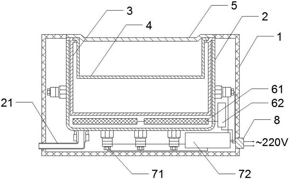
[0019] like figure 1 The shown ultrasonic cleaning machine includes a casing 1, a cleaning tank 2, a water outlet 21, a metal basket 3, a metal interlayer basket 4, a slot cover 5, a heater 61, a heater controller 62, a transducer 71, an ultrasonic Frequency power supply 72, socket 8;

[0020] The housing 1 is the frame of the whole equipment, the cleaning tank 2 is installed in the housing 1, and the drain port 21 is arranged at the bottom of the cleaning tank 1; the transducer 71 is bonded to the outer bottom wall of the cleaning tank 2; the transducer 71 is connected to the ultrasonic The frequency power supply 72, the ultrasonic frequency power supply 72 is connected to the socket 8, and the socket 8 is powered by 220V alternating current;

[0021] The heater 61 is installed in the cleaning tank 1, close to the bottom; the heater 61 is...


PUM


Abstract

An ultrasonic cleaning machine comprises a shell, a cleaning groove, a water draining opening, a metal bamboo crate, a metal interlayer bamboo crate, a groove cover, a heater, a heater controller, a transducer, an ultrasonic frequency power supply and a socket. The heater is arranged inside the cleaning groove, the metal interlayer bamboo crate comprises one layer or multiple layers, and is arranged in the cleaning groove, and small objects to be cleaned are placed in a multi-layer manner. On the basis of the scheme, the energy utilization rate and the space utilization rate of the ultrasonic cleaning machine are improved.

Description

technical field [0001] The invention relates to a cleaning device, in particular to an ultrasonic cleaning machine. Background technique [0002] The principle of the ultrasonic cleaning machine is mainly to convert the sound energy of the power ultrasonic frequency source into mechanical vibration through the transducer, and radiate the ultrasonic wave to the cleaning liquid in the tank through the cleaning tank wall. Due to the radiation of ultrasonic waves, the micro-bubbles in the liquid in the tank can keep vibrating under the action of sound waves. Destroy the adsorption of the dirt and the surface of the cleaning piece, causing the fatigue damage of the dirt layer to be separated, and the vibration of the gas-type bubbles scrubs the solid surface. [0003] The existing ultrasonic cleaning machine adopts the solution of external heating of the cleaning tank, and the energy utilization rate of this solution needs to be improved; and the utilization rate inside the exis...

Claims


Application Information

Patent Timeline
IPC IPC(8): B08B3/12B08B3/10B08B13/00
CPCB08B3/12B08B3/10B08B13/00B08B2203/007
Inventor 宋国明鲍观记张兄红
Owner ANHUI LVJIAN DETECTION TECH SERVICE CO LTD
Why Eureka
Try Eureka