Fiber laser cutting machine

A fiber laser, cutting machine technology, applied in laser welding equipment, welding equipment, metal processing equipment and other directions, can solve the problem of needing artificial feeding and other problems, and achieve the effect of saving labor

Inactive Publication Date: 2016-07-20
TIANJIN HONGGUANG WEIYE LASER TECH CO LTD
View PDF7 Cites 18 Cited by
  • Summary
  • Abstract
  • Description
  • Claims
  • Application Information

AI Technical Summary

Problems solved by technology

Although this utility model can save time and effort by providing rolling balls and sliding rods, it still needs manual feeding

Method used


Image

  • Fiber laser cutting machine
  • Fiber laser cutting machine
  • Fiber laser cutting machine

Examples


Embodiment Construction

[0026] First of all, it should be noted that the specific structure, characteristics and advantages of the fiber laser cutting machine of the present invention will be specifically described below by way of example, but all descriptions are for illustration only, and should not be understood as No limitations are imposed on the invention. In addition, any single technical feature described or implied in each embodiment mentioned herein, or any single technical feature shown or implied in each drawing, can still be described in these technical features (or their equivalents) ) to continue any combination or deletion, so as to obtain more other embodiments of the present invention that may not be directly mentioned herein. In addition, for the sake of simplifying the drawings, the same or similar technical features may only be marked in one place in the same drawing.

[0027] It will be understood that when a component is referred to as being "connected" to another component, i...


PUM

PropertyMeasurementUnit
angleaaaaaaaaaa

Abstract

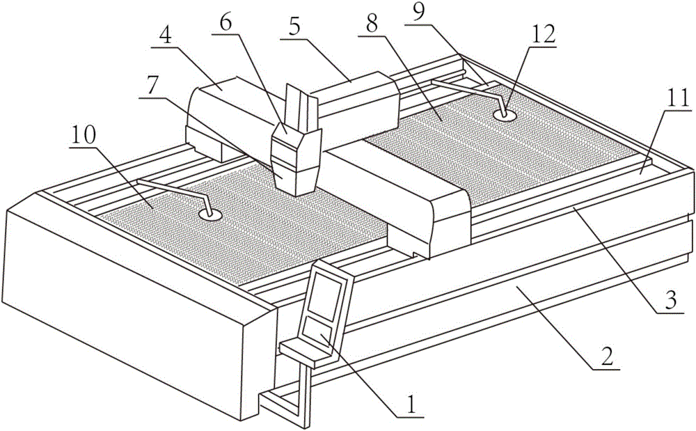
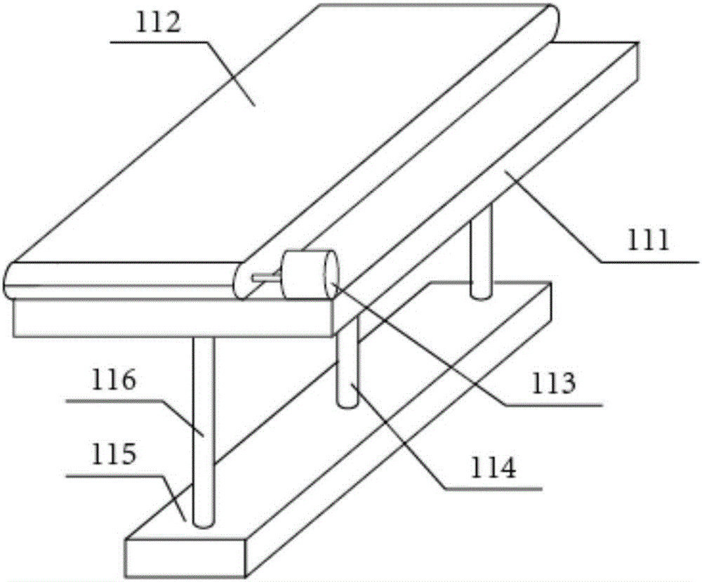
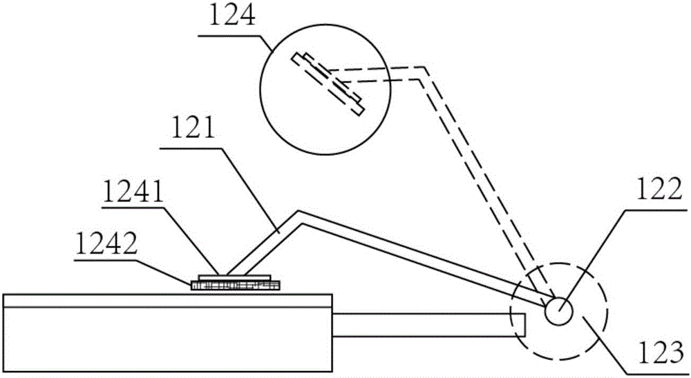
The invention relates to the field of laser cutting machines, in particular to a fiber laser cutting machine. The fiber laser cutting machine comprises a master control device, a work machine table, linear guide rails, a cross beam assembly, a transverse moving assembly, a height lifting assembly and a laser cutting head. The linear guide rails are arranged on the two sides of the work machine table in the length direction of the work machine table. The cross beam assembly is arranged between the two linear guider rails in a suspended manner and can slide along the two linear guide rails. The transverse moving assembly is arranged on the cross beam assembly and can slide in the length direction of the cross beam assembly. The height lifting assembly is fixed to the lower end of the transverse moving assembly. The laser cutting head is fixed to the lower end of the height lifting assembly. Two sets of conveying devices are arranged between two fixed bed frames and the work machine table. Each conveying device comprises a lifting table, a conveying belt and a motor for driving the conveying belt. The conveying belts and the motors are mounted on the lifting tables. The lifting tables and the motors are all connected with the master control device. According to the fiber laser cutting machine, automatic feeding can be achieved, and meanwhile a clamping device is arranged.

Description

technical field [0001] The invention relates to the field of laser cutting machines, in particular to an optical fiber laser cutting machine. Background technique [0002] The optical fiber laser processing equipment in the prior art generally only has one laser cutting area, that is, after cutting the corresponding incoming workpiece, it is necessary to unload the processed workpiece, and then load a new incoming workpiece to continue cutting, so As a result, even if the processing work is interrupted at intervals, the work continuity is poor, the production speed is slow, the production efficiency is low, and the processing cycle is long, which also makes various costs higher. Moreover, the existing optical fiber laser processing equipment does not have a very practical workpiece incoming transition device on the corresponding laser processing workbench, that is, when the incoming workpiece is installed on the corresponding workpiece support, the incoming workpiece The ma...

Claims


Application Information

Patent Timeline
Patent Type & Authority Applications(China)
IPC IPC(8): B23K26/38B23K26/08B23K26/70
CPCB23K26/0876B23K26/38B23K26/402B23K26/70
Inventor 刘明辉江勇朱秀梅
Owner TIANJIN HONGGUANG WEIYE LASER TECH CO LTD
Why Eureka
Try Eureka