3D printing and milling combined machine tool

A technology of 3D printing and compound machine tools, applied in the field of 3D printing, can solve the problems of poor printing accuracy, poor surface finish, and low printing efficiency

Inactive Publication Date: 2016-07-20
HARBIN DINGZHI RUIGUANG TECH CO LTD
View PDF1 Cites 9 Cited by
  • Summary
  • Abstract
  • Description
  • Claims
  • Application Information

AI Technical Summary

Problems solved by technology

However, the existing 3D printers have the problem of contradiction between printing efficiency and processing accuracy, that is, to obtain high-precision printing quality, thin slices are required, which leads to low printing efficiency, and to improve printing efficiency, printing accuracy and surface The finish is poor and subsequent surface treatment is required

Method used


Image

  • 3D printing and milling combined machine tool

Examples


Embodiment Construction

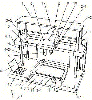
[0017] Such as figure 1 As shown, a 3D printing milling compound machine tool includes a frame 1, an X-axis motion component 2, a Y-axis motion component 3, a Z-axis lifting component 4, a feeding device 6, a nozzle device 5, a base 17 and a material transmission device 7 ;

[0018] The two ends of the two guide rails Z4-2 of the Z-axis motion assembly 4 are respectively rotatably connected to the top plate 1-2 and the base 17 of the frame 1, and the two motion slides Z4-1 of the Z-axis motion assembly 4 are connected to The four columns 1-1 of the frame 1 are slidingly connected, and the two moving slides Z4-1 of the Z-axis motion component 4 are threadedly connected with the two guide rails Z4-2 of the Z-axis motion component 4;

[0019] The two ends of the two guide rails X2-2 of the X-axis motion component 2 are respectively fixedly connected with the two motion slides Z4-1 of the Z-axis motion component 4, and the motion slide X2-1 of the X-axis motion component 2 is con...


PUM


Abstract

The invention discloses a 3D printing and milling combined machine tool, and belongs to the technical field of 3D printing. The 3D printing and milling combined machine tool is high in printing efficiency and machining precision. A drive motor is fixed to the upper surface of a motion sliding table X of an X-axis motion assembly. The output end of the drive motor penetrates the motion sliding table X of the X-axis motion assembly to be fixedly connected with the upper end of a rotary shaft. An opening is formed in the lower end of the rotary shaft. One of multiple milling tools is clamped in the opening of the rotary shaft, and the corresponding milling tool is connected with the opening of the rotary shaft through a bolt. A chip bearing groove is formed in a motion sliding table Y of a Y-axis motion assembly, and a machining platform is fixedly connected with the motion sliding table Y of the Y-axis motion assembly through a bolt. A discharging opening is formed in the motion sliding table Y of the Y-axis motion assembly, and a recycling box is arranged at the lower end of the discharging opening. According to the 3D printing and milling combined machine tool, a model is subjected to precision machining while 3D printing is achieved, printing efficiency is improved, and high-surface-quality machining precision can be achieved.

Description

technical field [0001] The invention belongs to the technical field of 3D printing, and in particular relates to a 3D printing and milling compound machine tool. Background technique [0002] 3D printing technology has been widely used in architectural design, medical assistance, industrial design, aerospace, food and animation models and other fields. However, the existing 3D printers have the problem of contradiction between printing efficiency and processing accuracy, that is, to obtain high-precision printing quality, thin slices are required, which leads to low printing efficiency, and to improve printing efficiency, printing accuracy and surface The finish is poor and subsequent surface treatment is required. Contents of the invention [0003] In view of the above problems, the present invention provides a 3D printing milling compound machine tool with high printing efficiency and high processing precision. [0004] The technical solution adopted by the present inv...

Claims


Application Information

Patent Timeline
Patent Type & Authority Applications(China)
IPC IPC(8): B29C67/00B33Y30/00B23C3/00B23Q11/00
CPCB33Y30/00B23C3/00B23Q11/0067
Inventor 廖新胜于广滨兰天浩
Owner HARBIN DINGZHI RUIGUANG TECH CO LTD
Why Eureka
Try Eureka