Speedboat and manufacturing method thereof

A manufacturing method and speedboat technology, applied in the direction of warships, ship construction, ship parts, etc., can solve the problems of increased production cost, complicated manufacturing process, easy deformation of the hull, etc., and achieve the goal of not easily deformed, less splashing, and less labor Effect

Inactive Publication Date: 2017-12-12
刘石全
View PDF6 Cites 0 Cited by
  • Summary
  • Abstract
  • Description
  • Claims
  • Application Information

AI Technical Summary

Problems solved by technology

Nowadays, speedboats are pursuing fast, stable, light and rigid. The speed of the boat must be fast, and the hull must be light, but the hull is light, and the stability is poor. Falling, seasickness and other problems; and to make the hull lighter, more keels, ribs and floating warehouses must not be added. Without these strengthening parts, the rigidity of the entire hull will be reduced. Therefore, the speedboat is fast, stable and light. The four indicators of rigidity and rigidity make small speedboats a contradictory body; because small speedboats are easy to manufacture, economical and practical, they still meet the needs of the public; thus, people have carried out various modifications to small speedboats, such as in order to make small speedboats fast. , to increase the propulsion power, but this will virtually increase the production cost
[0003] Furthermore, the existing speedboats have their hulls assembled and welded with metal plates one by one. The manufacturing process is complicated, there are many welding points, and the hull is easily deformed.

Method used


Image

  • Speedboat and manufacturing method thereof
  • Speedboat and manufacturing method thereof
  • Speedboat and manufacturing method thereof

Examples


Embodiment Construction

[0025] Below in conjunction with accompanying drawing example, the present invention is described in further detail:

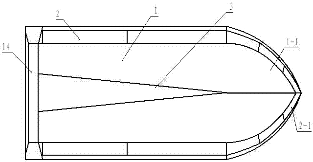
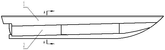
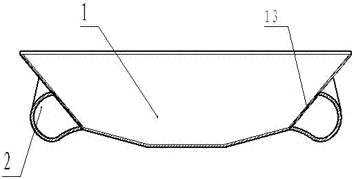
[0026] Such as Figure 1-Figure 3 As shown, the present embodiment includes a hull 1, and the two sides of the hull are symmetrically provided with buoys 2 along the knuckle lines of the hull. The buoys are closed long tanks with cavities inside. Bending downwards, the middle and rear part of the buoy 2 is attached to both sides of the hull 1 and slopes downward along the tail of the hull. The tail section of the buoy is lower than the waterline of the hull 1. When floating statically, the buoy is partially immersed in water and increases Lateral stability; because the bottom of the outer surface of the pontoon is bent downward, the bottom of the pontoon and the bottom of the hull form a wave dissipation channel. When the speed increases, the pontoon gradually jumps out of the water surface, reducing resistance and achieving the goal of fast driving; the ponto...


PUM


Abstract

The invention discloses a speed boat and a manufacturing method thereof and relates to the field of water surface boats. The speed boat comprises a hull. Floating barrels are symmetrically arranged on the two sides of the hull along knuckle lines of the hull. The floating barrels are closed long tank bodies with cavities formed inside. The bottoms of the outer side faces of the long tank bodies are bent downwards. The manufacturing method of the speed boat includes the steps that a metal plate is cut and developed into the hull with the floating barrels, side floating barrels communicating with the floating barrels of the hull are welded to the two sides of a bow, the side faces of the bow are welded to the side walls of the hull, and finally, a metal plate is pressed into a tail seal to be welded to the tail of the hull. Compared with the prior art, due to the fact that the closed floating barrels with the cavities formed inside are symmetrically arranged at the positions of the knuckle lines of the hull on the two sides of the hull, in the static floating process, part of the floating barrels are submerged in water, the reserved buoyancy of the floating barrels is greatly improved, the draught of the hull is greatly reduced, and the transverse stability performance is improved; when the speed is increased, the floating barrels gradually jump out of the water surface, resistance is reduced, and a rapid sailing target is achieved; and a rigid whole is composed of the floating barrels and the hull, and the structural strength is enhanced.

Description

technical field [0001] The invention relates to the technical field of surface ships, in particular to a speedboat and a manufacturing method thereof. Background technique [0002] A speedboat is a small boat that moves at high speed on the water surface. It is widely used in military and civilian fields. The speedboat is composed of a hull, propeller, steering wheel, engine and other components. Nowadays, speedboats are pursuing fast, stable, light and rigid. The speed of the boat must be fast, and the hull must be light, but the hull is light, and the stability is poor. Falling, seasickness and other problems; and to make the hull lighter, more keels, ribs and floating warehouses must not be added. Without these strengthening parts, the rigidity of the entire hull will be reduced. Therefore, the speedboat is fast, stable and light. The four indicators of rigidity and rigidity make small speedboats a contradictory body; because small speedboats are easy to manufacture, eco...

Claims


Application Information

Patent Timeline
Patent Type & Authority Patents(China)
IPC IPC(8): B63B43/14B63B1/32B63B9/06
CPCB63B1/32B63B43/14B63B73/00B63B2221/02Y02T70/10
Inventor 刘石全
Owner 刘石全
Why Eureka
Try Eureka