Supercharge Your Innovation With Domain-Expert AI Agents!

Special light bridge erecting machine for hollow slab

A hollow slab and bridge erecting machine technology, which is applied in the direction of erecting/assembling bridges, bridges, and bridge construction, etc., can solve the problems of overall bulkiness, high cost, inconvenient disassembly and assembly of bridge erecting machines, and achieves simple structure and convenient disassembly and assembly. , the effect of convenient operation

Active Publication Date: 2017-08-25
GUIZHOU ROAD & BRIDGE GRP
View PDF7 Cites 0 Cited by
  • Summary
  • Abstract
  • Description
  • Claims
  • Application Information

AI Technical Summary

Problems solved by technology

However, the large-tonnage bridge erecting machine is generally heavy, inconvenient to disassemble and assemble, and difficult to transport. Not only is it overkill, but it is also expensive

Method used


Image

  • Special light bridge erecting machine for hollow slab
  • Special light bridge erecting machine for hollow slab
  • Special light bridge erecting machine for hollow slab

Examples


Embodiment Construction

[0024] The specific implementation, structure, features and functions of the light bridge erecting machine for hollow slabs according to the present invention will be described in detail below in conjunction with the accompanying drawings and preferred embodiments.

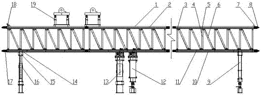
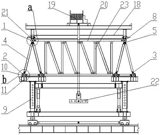
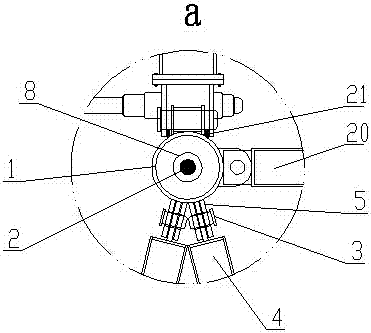
[0025] see Figure 1 to Figure 3 , the special light-duty bridge erecting machine for hollow slabs of the present invention, including "A" type main girder, front outrigger 9, middle outrigger 12, middle and auxiliary outrigger 13, rear outrigger 16, crane crane 19, "A" There are front outriggers 9, middle outriggers 12, middle and auxiliary outriggers 13, and rear outriggers 16 connected in sequence under the main girder, wherein: the upper chord 1 and the lower chord 10 of the "A" main girder are connected with a web A4 and the web B6, the lower chord beam 11 is installed between the lower chord 10, the upper chord 1 and the lower chord 10 are equipped with longitudinal prestressed steel bars 2, and the top of t...


PUM


Abstract

The invention discloses a special light type bridge girder erection machine for hollow slabs. The special light type bridge girder erection machine comprises A-shaped main beams, front landing legs (9), a middle landing leg (12), an assistant middle landing leg (13), rear landing legs (16) and a hoisting overhead travelling crane (19), wherein the front landing legs (9), the middle landing leg (12), the assistant middle landing leg (13) and the rear landing legs (16) are sequentially connected to the lower sides of the A-shaped main beams. The special light type bridge girder erection machine is characterized in that a web member A (4) and a web member B (6) are connected between an upper chord (1) and a lower chord (10) of each A-shaped main beam, a lower chord cross beam (11) is arranged between the lower chords (10), longitudinal prestressed reinforcements (2) are arranged in the upper chords (1) and the lower chords (10), the movable hoisting overhead travelling crane (19) is arranged on the top of the upper chords (1), and a lifting appliance (22) is arranged under the hoisting overhead travelling crane (19). The special light type bridge girder erection machine has a simple structure, can be operated conveniently, is safe and stable, can be installed and detached conveniently, and is suitable for popularization and application of hollow slab bridging.

Description

technical field [0001] The invention belongs to the technical field of bridge construction devices, and in particular relates to a special light bridge erecting machine for hollow slabs. Background technique [0002] In the reconstruction projects of high-grade highways, municipal public works and upgraded old roads, there are often large and medium bridges with 22m hollow slabs. Because of their small span, light weight of the beam body and low requirements for construction machinery, they are popular in the industry. widespread favor. [0003] In areas with flat terrain, the installation of the 22m hollow slab is relatively easy. Two 25-ton cranes can be used to install the hollow slab at both ends of the beam and slab. However, in mountainous and hilly areas, the installation of 22m hollow slabs is relatively difficult. On the one hand, the terrain under the bridge span has large fluctuations, or crosses valleys, rivers, or crosses existing highways, etc., and the trans...

Claims


Application Information

Patent Timeline
Patent Type & Authority Patents(China)
IPC IPC(8): E01D21/00
CPCE01D21/00
Inventor 韩洪举左卿彭力廖正杰伍亭垚谢海波王国丰王梦薇叶静王锁肖明钧
Owner GUIZHOU ROAD & BRIDGE GRP
Features
  • R&D
  • Intellectual Property
  • Life Sciences
  • Materials
  • Tech Scout
  • Unparalleled Data Quality
  • Higher Quality Content
  • 60% Fewer Hallucinations
Learn More