Continuously moving oil rig as well as pull-out and run-in methods thereof

A motion and oil technology, applied in the fields of continuous motion tripping, continuous motion oil drilling rig, and continuous motion drilling down, can solve the loss of circulation, well collapse, impact on the stability of the wellbore wall, and impact on the bottom hole in the fractured formation. Drilling rig work efficiency and other issues, to achieve the effect of less impact of bottom hole pressure fluctuations, improved wellbore stability, and increased tripping speed

Active Publication Date: 2016-07-20
BAOJI PETROLEUM MASCH CO LTD +2
View PDF7 Cites 6 Cited by
  • Summary
  • Abstract
  • Description
  • Claims
  • Application Information

AI Technical Summary

Problems solved by technology

[0005] The purpose of the present invention is to provide a continuous motion oil drilling rig, which solves the problem of frequent acceleration and deceleration in the tripping process of the prior art, which not only affects the working efficiency of the drilling rig, but also causes high energy consumption of the drilling rig; The pumping of the drilling fluid causes wellbore pressure fluctuations, which in turn affects the stability of the wellbore wall; during the run-in process, due to the high speed of the run-in, the bottom-hole pressure fluctuates greatly, which may easily lead to fractured formations Well leakage and well collapse

Method used


Image

  • Continuously moving oil rig as well as pull-out and run-in methods thereof
  • Continuously moving oil rig as well as pull-out and run-in methods thereof
  • Continuously moving oil rig as well as pull-out and run-in methods thereof

Examples


Embodiment Construction

[0044] The present invention will be described in detail below in conjunction with the accompanying drawings and specific embodiments.

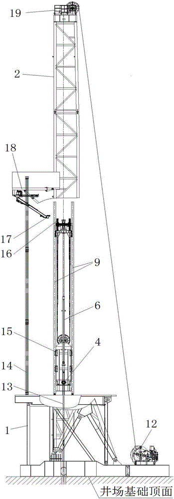
[0045] The turntable and turntable beam of conventional oil drilling rigs are installed on the base and cannot move up and down along the center line of the vertical wellhead. The present invention is designed to increase a set of rotating disk lifting mechanism for rotating disk 4 on the basis of conventional oil drilling rigs.

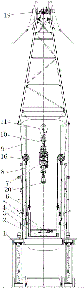
[0046] refer to figure 1 , figure 2 , the structure of the continuous motion oil drilling rig of the present invention is that the derrick 2 is installed on the base 1 of the rig, and two sets of hoisting mechanisms are arranged in the derrick 2, one set is the top drive hoisting mechanism for the top drive 7, and the other is for the top drive 7. The turntable lifting mechanism of turntable 4,

[0047] The top drive hoisting mechanism is the same in structure as the top drive hoisting mechanism of conventional ...


PUM


Abstract

The invention discloses a continuously moving oil rig. The oil rig comprises two lifting mechanisms, namely, a top drive lifting mechanism and a rotary disc lifting mechanism, wherein the rotary disc lifting mechanism adopts such a structure that a rotary disk guide rail on each side in a derrick is configured with a pulley and the lower end of the pulley on each side is connected with a hydraulic cylinder; a rotary disc steel wire rope winds around the pulley on each side, one end of the rotary disc steel wire rope is fixed on a base, the other end of the rotary disc steel wire rope winds around a pulley block on a rotary disc beam or is directly fixed on the rotary disc beam, a rotary disc beam guide mechanism is arranged on each of left and right sides of the rotary disc beam, and the rotary disc beam guide mechanisms on the two sides are sleeved with the respective rotary disc guide rails; a rotary disc and a slip of the rotary disc are mounted in the center of the rotary disc beam. The invention further discloses a continuously moving pull-out method and a continuously moving run-in method. The oil rig is simple in structure, and the two methods work reliably and are convenient to operate.

Description

technical field [0001] The invention belongs to the technical field of oil drilling rigs, is applicable to land and sea drilling rigs and workover rigs, and relates to a continuous motion oil drilling rig; in addition, the invention also relates to a continuous motion drilling method and a continuous motion drilling method. Background technique [0002] During the tripping process of the conventional oil drilling rig, after the first column is lifted, the drill string is supported by slips and rests on the fixed turntable, and the first column (usually 3 drill pipes to form a 1 Drill pipe joint connected with the drill string, the column is discharged to the second floor platform, and the top drive is lowered. After the top drive is lowered to the set height, the top drive elevator is opened and fastened under the drill pipe joint at the top of the drill string. , lift the drill string, the slips on the turntable are opened, and then the drill string can continue to be lifte...

Claims


Application Information

Patent Timeline
Patent Type & Authority Applications(China)
IPC IPC(8): E21B19/00
CPCE21B19/00
Inventor 周忠祥黄悦华王维旭杨刚于浩
Owner BAOJI PETROLEUM MASCH CO LTD
Why Eureka
Try Eureka