Sliding plate rotor engine

A rotary engine and skateboard technology, applied in engine components, machines/engines, mechanical equipment, etc., can solve the problems of low efficiency, unreasonable structure, large weight, etc., and achieve high efficiency, low mechanical vibration and wear, and low power consumption. Effect

Inactive Publication Date: 2016-07-20
苗军
View PDF5 Cites 2 Cited by
  • Summary
  • Abstract
  • Description
  • Claims
  • Application Information

AI Technical Summary

Problems solved by technology

[0003] The purpose of the present invention is to provide a skateboard rotor engine to overcome the defects of

Method used


Image

  • Sliding plate rotor engine
  • Sliding plate rotor engine
  • Sliding plate rotor engine

Examples


Embodiment 1

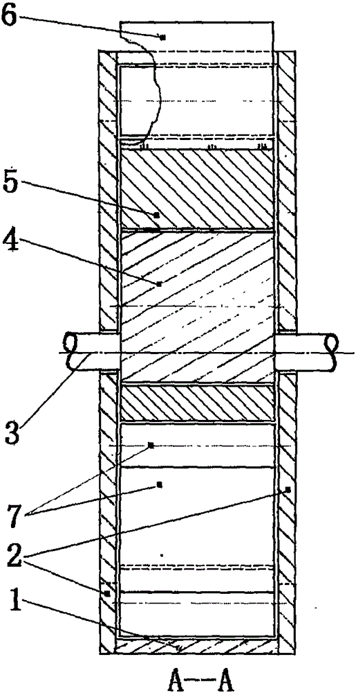
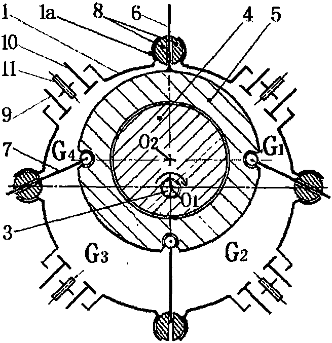
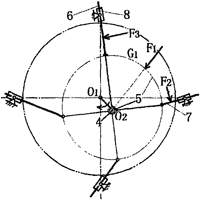
[0017] Such as figure 1 , 2 As shown, in the skateboard rotor engine of the present invention, the two ends of the cylindrical stator 1 are closed by the end cover 2, and the built-in engine main shaft 3 is supported in the center of the end cover, and the eccentric wheel 4 connected thereon is covered with a skateboard ring for rotation fit. 5. The surface of the skateboard ring is fixed with a radial fixed skateboard. 6. Three outward hinged skateboards are hinged. 7. Each skateboard is evenly distributed on the skateboard ring. The inner wall of the cover is used for sliding and sealing fit. On the outer wall of the stator facing each slide plate, a longitudinal shaft seat 1a is respectively provided. The connection between each shaft seat and the stator wall and the opposite side are provided with a full length wider than the thickness of the slide plate. Notch, each shaft seat is equipped with a circular shaft body 8 for rotating and sealing fit, each slide plate penetra...

Embodiment 2

[0031] On the basis of the skateboard rotor engine described in Embodiment 1, a fixed slide plate 6 is still retained, and the hinged slide plate 7 that is hinged to the slide plate ring 5 is changed from the original three to two, and each slide plate is on the slide plate. Evenly distributed on the ring, on the outer wall of the stator facing each slide plate, a longitudinal shaft seat 1a is respectively arranged, and the connection between each shaft seat and the stator wall and the opposite side are provided with a full-length gap wider than the thickness of the slide plate. Each shaft seat is equipped with a circular shaft body 8 for rotating and sealing fit, each slide plate penetrates radially along the round shaft body and performs sliding and sealing fit, and an air inlet is provided on the stator wall between two adjacent shaft seats. Valve 9, exhaust valve 10, spark plug 11 (as Figure 15 Shown), other structures and operating principles of the engine are as in Embo...

Embodiment 3

[0033] On the basis of the skateboard rotor engine described in Embodiment 1, a fixed slide plate 6 is still retained, and the hinged slide plate 7 that is hinged to the slide plate ring 5 is changed from the original three to four, and each slide plate is on the slide plate. Evenly distributed on the ring, on the outer wall of the stator facing each slide plate, a longitudinal shaft seat 1a is respectively arranged, and the connection between each shaft seat and the stator wall and the opposite side are provided with a full-length gap wider than the thickness of the slide plate. Each shaft seat is equipped with a circular shaft body 8 for rotating and sealing fit, each slide plate penetrates radially along the round shaft body and performs sliding and sealing fit, and an air inlet is provided on the stator wall between two adjacent shaft seats. Valve 9, exhaust valve 10, spark plug 11 (as Figure 16 Shown), other structures and operating principles of the engine are as in Emb...


PUM


Abstract

The invention discloses a sliding plate rotor engine. The sliding plate rotor engine is characterized in that two ends of a barrel-shaped stator (1) are closed through end covers (2); an internally arranged engine spindle (3) is supported on the centers of the end covers; an eccentric wheel (4) which is connected onto the engine spindle (3) is sleeved with a sliding plate ring (5); the sliding plate ring is fixedly connected with a radial fixedly-connected sliding plate (6) and is hinged to a group of outward hinge-connection sliding plates (7); the end surfaces of two ends of each of the eccentric wheel, the sliding plate ring and the sliding plates are in sliding and sealing match with the inner walls of the end covers; the parts, which face the sliding plates, of the outer wall of the stator are each provided with a longitudinal shaft seat (1a); a round shaft body (8) is arranged in each shaft seat (1a); the sliding plates radially penetrate through the corresponding round shaft bodies and are in sliding and sealing match with the corresponding round shaft bodies; and the part, between every two adjacent shaft seats, of the stator wall is provided with an air inlet valve (9), an air exhaust valve (10) and a sparking plug (11). The inner cavity of the stator is divided into a plurality of sealed air chambers through the sliding plates; and the volume of each chamber is increased and decreased regularly along with the rotation of the spindle, so that circulation of air suction, compression, working and air exhaust is realized. Rotation power is directly output; the structure is simplified; the heat efficiency is high; the power consumption is low; the size is small; and the mass is light.

Description

[0001] Technical Field: The present invention relates to an engine, in particular to a skateboard rotor engine. Background technique [0002] The reciprocating piston engine has many reciprocating parts, plus a heavy crank-link mechanism, which makes it have large harmful inertia, bulky parts, high power consumption, large vibration, and fast wear. Through extensive searches, no technical solutions identical to the present invention have been found. Contents of the invention [0003] The object of the present invention is to provide a skateboard rotor engine for overcoming the defects of large volume, heavy weight and low efficiency caused by the unreasonable structure of the reciprocating piston engine. [0004] The technical solution adopted by the present invention to solve its technical problems is: [0005] A skateboard rotor engine, characterized in that: the two ends of the cylindrical stator are closed by the end cover, the engine main shaft is supported in the cent...

Claims


Application Information

Patent Timeline
IPC IPC(8): F02B77/00
CPCF02B77/00
Inventor 苗军
Owner 苗军
Why Eureka
Try Eureka