Double-refrigerant circulating natural gas liquefaction system based on wound-tube heat exchanger

A coiled-tube, natural gas technology, applied in refrigeration and liquefaction, liquefaction, climate sustainability, etc., can solve problems such as inability to meet offshore production conditions, complex system processes, and large equipment size, reducing engineering costs. The effect of construction difficulty and project investment cost, streamlined system process and compact structure

Inactive Publication Date: 2016-07-20
CHINA NAT OFFSHORE OIL CORP +1
View PDF8 Cites 7 Cited by
  • Summary
  • Abstract
  • Description
  • Claims
  • Application Information

AI Technical Summary

Problems solved by technology

Although this type of natural gas liquefaction process has a high production capacity, the system process is too complicated, the equipment size is large and the investment cost is high, so it cannot better meet the offshore production conditions

Method used


Image

  • Double-refrigerant circulating natural gas liquefaction system based on wound-tube heat exchanger
  • Double-refrigerant circulating natural gas liquefaction system based on wound-tube heat exchanger
  • Double-refrigerant circulating natural gas liquefaction system based on wound-tube heat exchanger

Examples


Embodiment

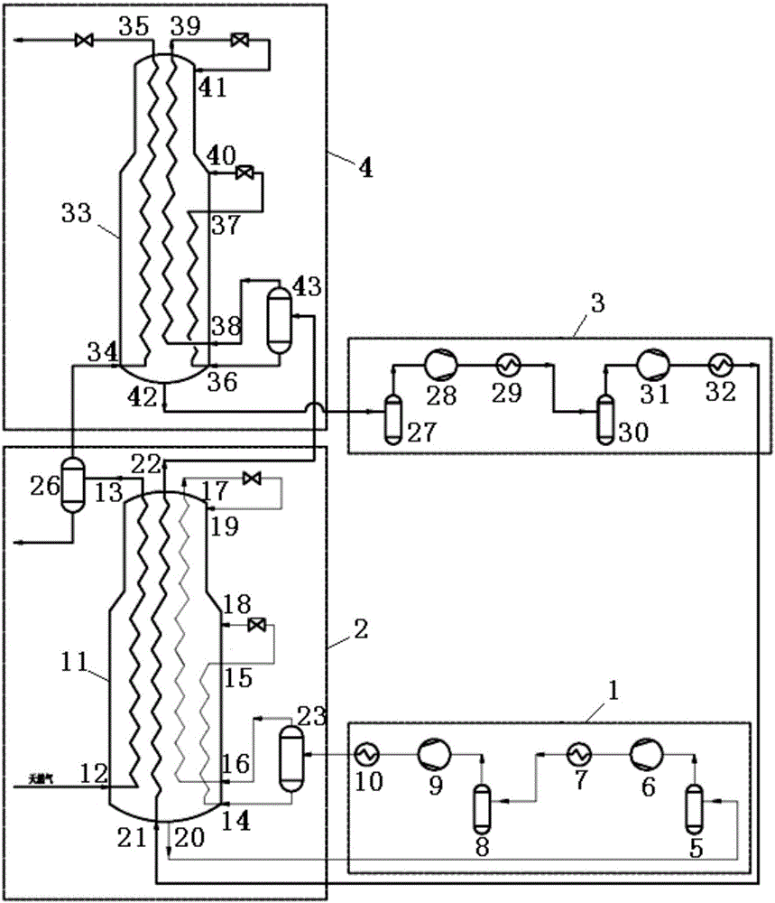
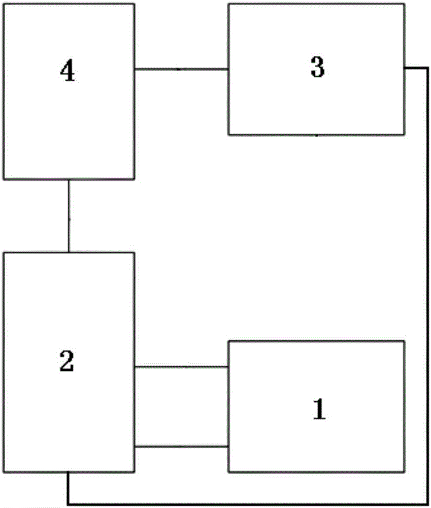
[0034] The liquefaction system provided by the present invention is used to develop and utilize an offshore gas field. Firstly, the purified raw natural gas (at a temperature of 45.0°C and a pressure of 4.0MPaA) is introduced into the main low-temperature heat exchanger 11 for pre-cooling, and the pre-cooled mixed refrigerant Cool to -50°C, enter the gas-liquid separator 26 for gas-liquid separation, the separated condensate is connected to the outside from the bottom of the separator, and the gas-phase natural gas obtained after separation enters the main low-temperature heat exchanger 33 for low-temperature liquefaction, and is cryogenically mixed The refrigerant is cooled to -153°C, throttled through the throttle valve, and the pressure is reduced to 0.2MPaA, and the produced LNG is led out to external storage.

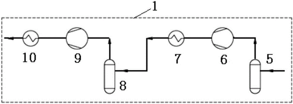
[0035] The low-pressure precooling mixed refrigerant (temperature 19.0°C, pressure 0.21MPaA) from the main low-temperature heat exchanger 11 is sequentially compres...


PUM


Abstract

The invention provides a double-refrigerant circulating natural gas liquefaction system based on a wound-tube heat exchanger. The double-refrigerant circulating natural gas liquefaction system is characterized by comprising a precooling level compression module, a precooling level heat exchange module, a copious cooling level compression module and a copious cooling level heat exchange module which are connected, wherein the precooling level compression module comprises buffer tanks, compressors and coolers which are connected in sequence; a precooling refrigerant low-pressure outlet of the precooling level heat exchange module is connected with one of the buffer tanks; a natural gas first-level outlet is connected with a gas-liquid separator; the outlet of one of the coolers is connected with another gas-liquid separator; the copious cooling level compression module comprises buffer tanks, compressors and coolers which are connected in sequence; a copious cooling refrigerant low-pressure outlet of the copious cooling level heat exchange module is connected with one of the buffer tanks of the copious cooling level compression module; a natural gas second-level outlet is connected with the exterior; a natural gas second-level inlet is connected with one of the gas-liquid separators; the outlet of one of the coolers of the copious cooling level compression module is connected with a copious cooling refrigerant first-level inlet; and a copious cooling refrigerant first-level outlet is connected with a gas-liquid separator of the copious cooling level heat exchange module. According to the double-refrigerant circulating natural gas liquefaction system, two-level independent mixed refrigerants circulate and are overlaid, the system process is concise, the structure is compact, the production load operational flexibility is high, the integral machine adopts modularized design, and the system is applicable to offshore flotation natural gas production devices.

Description

technical field [0001] The invention relates to a natural gas liquefaction system, in particular to a natural gas liquefaction system with double refrigerant cycles based on a coiled tube heat exchanger. Background technique [0002] LNG (Liquefied Natural Gas, liquefied natural gas) is to cool the treated gaseous natural gas under normal pressure to -162°C to condense it into liquid. The liquid volume of LNG is about 1 / 600 of its gaseous volume, which greatly saves storage and transportation space and cost, and has the characteristics of large calorific value and high performance. Therefore, LNG is a clean and efficient energy source. [0003] Natural gas liquefaction process mainly includes three types: cascade liquefaction process, mixed refrigerant liquefaction process and liquefaction process with expander. Among them, the cascade liquefaction process unit is too complicated and the investment cost is high, and it is mainly used in the early base-load liquefaction plan...

Claims


Application Information

Patent Timeline
Patent Type & Authority Applications(China)
IPC IPC(8): F25J1/02
CPCF25J1/0212F25J1/0022F25J1/0055F25J1/0214F25J1/0259F25J1/0292Y02P80/10
Inventor 陈杰曾伟平鹿来运褚洁张晓慧
Owner CHINA NAT OFFSHORE OIL CORP
Why Eureka
Try Eureka