Computer-vision-based underwater laser datum line measuring system

A computer vision and underwater laser technology, applied in the field of computer vision and underwater engineering, can solve the problems of many ships and machines, low efficiency, large investment, etc., and achieve the effect of simplifying cumbersome procedures

Inactive Publication Date: 2016-07-20
WUHAN HUAHAICHUANGZHI TECH CO LTD
View PDF14 Cites 5 Cited by
  • Summary
  • Abstract
  • Description
  • Claims
  • Application Information

AI Technical Summary

Problems solved by technology

The first four methods are all physical contact methods, which require a large number of personnel and ship machinery, which requires a large investment and low efficiency, and the surface hoisting commander can only obtain the position information of the underwater block through the underwater intercom and the diver’s voice communication , the construction quality cannot be effectively supervised
On the basis of this demand, a fifth method has been further developed - the measuring frame positioning method, that i

Method used


Image

  • Computer-vision-based underwater laser datum line measuring system
  • Computer-vision-based underwater laser datum line measuring system
  • Computer-vision-based underwater laser datum line measuring system

Examples


Embodiment Construction

[0023] In order to make the object, technical solution and advantages of the invention clearer, the present invention will be further described in detail below in conjunction with the accompanying drawings and embodiments. It should be understood that the specific embodiments described here are only used to explain the present invention, not to limit the present invention. In addition, the technical features involved in the various embodiments of the present invention described below can be combined with each other as long as they do not constitute a conflict with each other.

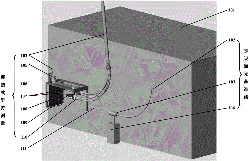
[0024] figure 1 It is a schematic diagram of the layout of the measurement components and the laser reference line transmitter when the underwater block is installed and measured. The measurement part of the computer vision-based underwater laser reference line measurement system includes portable handheld measurement components (102, 105, 106, 108, 109, 110) and preset laser reference line components ...


PUM


Abstract

The invention, which belongs to the underwater special measurement field, discloses a computer-vision-based underwater laser datum line measuring system for measuring a relative position parameter for underwater structure installation and assisting in underwater engineering building. According to the measuring system, a laser ray generated by a high-power laser is used as a preset datum line and a measuring scale, thereby providing an image feature for computer vision software measurement. An underwater camera carried by the system obtains an underwater on-the-spot picture; the computer vision software extracts an image feature; a relative distance between an underwater structure and a preset position is obtained by using a built-in algorithm; and a difference of elevation or a tooth malocclusion parameter between two adjacent regular structures is measured by extracting other features of the picture. Therefore, a plane attitude or relative position of a structure can be reflected; and an objective of assisting in precise installation of underwater work can be achieved.

Description

technical field [0001] The invention belongs to the technical fields of computer vision and underwater engineering, and in particular relates to computer vision recognition and measurement of underwater structures. Background technique [0002] Gravity wharf is a type of wharf structure that is widely distributed and widely used in my country. The main forms are block structure and caisson structure. Among them, the block-structured wharf generally uses prefabricated large concrete blocks as the basic components, and the blocks are prefabricated in the prefabrication yard, and then transported to the site for installation. The installation accuracy and efficiency of the blocks directly affect the quality and progress of the entire block dock construction. [0003] At present, in the construction of gravity block wharf, there are several traditional block installation measurement and positioning methods: underwater datum line method, front reference object control method, wa...

Claims


Application Information

Patent Timeline
IPC IPC(8): G01B11/02
CPCG01B11/022
Inventor 袁国强荀思瑞王文晋陈蔚然张玮康刘畅
Owner WUHAN HUAHAICHUANGZHI TECH CO LTD
Why Eureka
Try Eureka